Crop Production
Controlling the greenhouse environment can be challenging because greenhouses have a great capacity to gain heat during the day and lose heat rapidly due to low nighttime temperatures. The fundamental principles behind managing a greenhouse environment can be widely applied, regardless of the purpose.
This document conveys the basic principles and technologies used to heat and cool facilities that produce greenhouse vegetables in the southeastern United States. We highly recommend seeking professional expertise when designing a greenhouse and sizing its environmental controls. The capital cost is too great to risk mistakes in design.
Greenhouse Ventilation & Cooling
In the southeastern United States, greenhouses require ventilation year-round. Even in winter months, greenhouse temperatures can rise to damaging levels on clear days. Ventilation needed to prevent extreme heat can result in yield loss or crop failure.
Reducing greenhouse temperatures may include natural or mechanical ventilation, evaporative cooling, and shading. Understanding how a greenhouse is cooled and the limitations of the different cooling methods is essential in becoming an effective greenhouse manager.
Understanding Greenhouse Heat Gain & Influence of Greenhouse Height
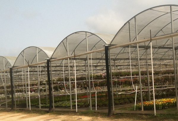
Figure 1. Modern high-walled greenhouse.
Heat gain is accomplished in greenhouses through the capture of solar radiation. Short wavelengths of light enter a greenhouse through the transparent glazing (covering) and are absorbed and reradiated as long wavelengths. The longer wavelengths are unable to pass through the glazing as fast as the shorter waves, which results in the greenhouse temperature increasing as the air volume continues to gain heat energy. In the past, low-ceiling greenhouses were used to keep warm air near the crop canopy. Current trends in greenhouse design have higher ceiling heights to increase greenhouse air volume (figure 1). By increasing the air volume, greenhouse structures can better buffer temperature changes.
The larger the volume, the greater the ability of the air to buffer temperature change. Consider two pots of water of the same size on a stove top. One pot is half filled, and the other pot is full. If both burners are set to boil, then the pot that is half full will reach boiling much faster. The half-full pot has a lower heat capacity because of the lower water content. The same phenomenon occurs with greenhouse volumes. As the height of the greenhouse increases, the surface area exposed to solar radiation does not increase proportionally to the greenhouse volume. Figure 2 illustrates two freestanding greenhouses with 30-foot x 96-foot floor areas. Greenhouse A has a 15-foot-tall sidewall, and greenhouse B has a 5-foot side wall. The total air volume for greenhouse A is 59,000 feet3 while greenhouse B is 37,000 feet3. Greenhouse A has almost 60 percent more air volume per square foot of floor area when compared to greenhouse B. Greenhouse B, however, has about 25 percent more surface area exposed to solar radiation per cubic foot of air volume when compared to greenhouse A. This results in a faster heat gain for the shorter ceiling greenhouse B.
Modern greenhouses use high ceiling heights to help buffer temperature changes, thereby increasing the volume-to-floor ratio. Currently, little to no research exists to identify the most efficient greenhouse design for Alabama’s climate. Sidewall heights of 8 feet or greater anecdotally seem to handle summer temperatures better than shorter houses. The current industry mindset is the taller, the better; however, taller houses may cost more per area.

Figure 2. Volumetric and surface area comparisons of two 30′ x 96′ free standing greenhouses with different sidewall heights.
Natural Ventilation
Natural ventilation capitalizes on outside air movement to push and pull hot air out of the greenhouse through ventilation areas in walls or roofs. The wind is the driving force behind the majority of natural ventilation. Even a small amount of wind can effectively push air through the greenhouse, where as little as a 3-miles per hour current can successfully ventilate most properly designed structures. To prevent heat gain, exchanging the greenhouse air volume once per minute through ventilation is necessary—the greater the ventilation area, the more an opportunity for air exchange. The American Society of Agricultural and Biological Engineers recommends ventilation of 15 percent to 25 percent of the floor area; however, Alabama’s extreme summer temperatures likely require an even greater ventilation area.
Increasing the ventilation area per area of greenhouse floor space is primarily achieved by increasing the sidewall height of the greenhouse and using that additional surface area for ventilation openings. Consider this concept early in the design phase of a greenhouse enterprise. The degree of ventilation is much more variable in the cooler months as outside air temperatures are considerably lower. Raising and lowering curtains depending on outside temperatures can reduce sudden drops in inside air temperatures. Controlling temperatures manually can be difficult as it would require constantly checking temperatures inside the structure. Mechanized curtain systems can be integrated with computerized environmental controls to automate ventilation systems during cooler times of the year (figure 3.)
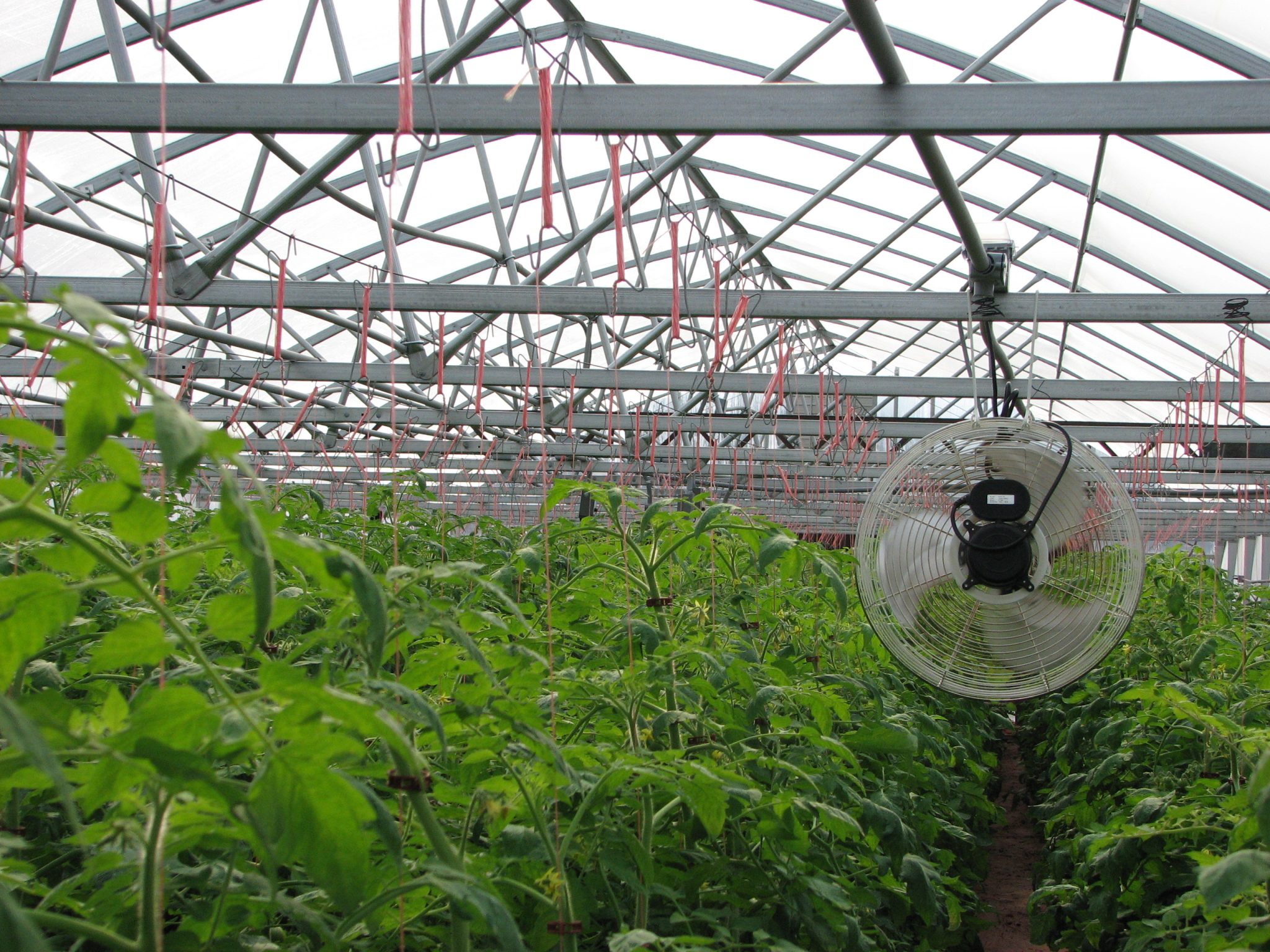
Consistency and uniformity are common issues with wind-driven ventilation systems throughout greenhouses. The larger the greenhouse area, the more likely the opportunity for stagnant air pockets. In some cases, circulating fans are used to aid in preventing these pockets (figure 4).
Large gutter-connected ranges can reduce the cost of structures per area; however, smaller ranges may be more effective in ventilation as the ratio of ventilation area per floor area decreases with an increasing structure floor area.
Buoyancy can also be an effective tool in ventilation as warm, humid air rises. If roof ventilation is available, a vacuum effect occurs as warm air exits through the roof and pulls fresh cooler air from the side vents. Greenhouses in tropical areas often use roof ventilation; however, few greenhouses in Alabama have adopted the technology.
-

- Figure 3. Automated curtain system on greenhouse side wall.
-
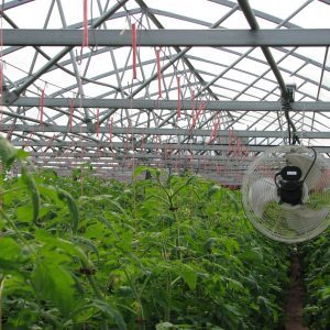
- Figure 4. Horizontal air fan (HAF).
-
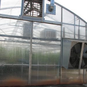
- Figure 5. Greenhouse exhaust fans.
Mechanical Ventilation
As previously mentioned, a tremendous amount of heat energy is captured and retained in the greenhouse. Greenhouse exhaust fans (figure 5) remove warm air while providing uniform air distribution across the entire greenhouse. There are many things to consider when sizing mechanical ventilation. To prevent stagnant air pockets, the space between fans should not exceed 25 feet. Limit greenhouse lengths to 150 feet to optimize fan performance. Fans should also exhaust air in the same direction as the prevailing winds. The manufacturer or engineer may suggest increasing your ventilation capacity if this is not an option. Any restriction on the intake or exhaust side of the greenhouse can reduce fan efficiency. Vents responsible for bringing fresh air in should be around 1.25 to 1.5 times the combined area of all exhaust fans.
A rule of thumb for sizing fans is to have the capacity to exchange 1.0 to 1.5 times the air volume of the greenhouse each minute. If a greenhouse air exchange rate of 1.5 greenhouse volumes per minute is desired, multiply the total greenhouse volume by 1.5. The volume exchange rate necessary for effective cooling depends on your area, and greenhouse manufacturers may use a higher exchange rate depending on the location and design of the structure. When sizing a ventilation system, it is common to limit the height in the greenhouse volume calculation to 8 to 10 feet. The air volume above these heights is considered stagnant and not always included in the calculation.
Calculating CFM for Fan Sizing
CFM to Exchange = Floor Area (ft2) × (8 or 10 ft) × Exchange Rate (1 or 1.5)
Once the total cubic feet per minute (cfm) is known, fans can be selected. Most fan manufacturers have performance charts for each fan model. These charts list the cfm based on the fan blade size, the motor horsepower, and the static pressure (table 1). The total cfm needed will be designed to cover two or more fans so air is distributed through the greenhouse and to have backup equipment in case one unit malfunctions. For example, if a total cfm is 40,000, it is common to choose two fans with a capacity of 20,000 cfm, or one may choose three to four fans. Nevertheless, this concept is sufficient as long as the total output requirement is attained.
Design parameters can be subjective, so it is important that whoever is sizing your fans understand your geographical location and the environment associated with it. If you use a greenhouse manufacturer or an engineer not located in your region, it would be wise to get input from other growers in your area.
Table 1. Fan Performance Data
| Blade Size (inches) | Motor HP | Fan Output (CFM) – 0.05′′ SP1 | Fan Output (CFM) – 0.10′′ SP |
|---|---|---|---|
| 36 | 1/2 | 10,308 | 9,553 |
| “ | 3/4 | 11,911 | 11,253 |
| 48 | 3/4 | 18,180 | 16,989 |
| “ | 1 | 20,628 | 19,563 |
Evaporative Cooling
Evaporative cooling has been a major tool in cooling greenhouse air. When water evaporates, the energy needed to change it from a liquid state to a vapor state is removed from the air and subsequently causes a cooling effect. However, the potential to evaporate water depends largely on relative humidity. Air can only hold so much water vapor, the higher the humidity, the lower the potential for evaporation. For this reason, evaporative cooling is significantly more efficient in arid regions. Despite the majority of the Southeast having a high degree of humidity, greenhouse operators still rely on evaporative cooling.
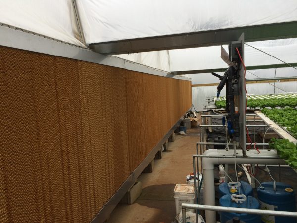
Figure 6. Evaporative cooling pad with cellulosic corrugated pad.
Evaporative cooling can be employed through evaporative cooling pads (figure 6), through high-pressure fog systems, or a combination of both. Evaporative cooling pad systems pull air through a pad of saturated material with a high surface area. The pad material may be made of matted aspen wood fibers or corrugated cellulosic panels, the latter being more common. Corrugated cellulosic pads may be sized with 4-inch or 6-inch thick pads. To maintain constant moisture on the pads, water is pumped over the pad and a thin film of water drips down the pad. Exhaust fans on the opposite side of the greenhouse pull outside air across the surface area of the pad. The air movement combined with the high degree of surface area promotes rapid evaporation. Even with evaporative cooling in place, the air temperature can still rise higher than 7 degrees F as air travels from the cooling pads to the exhaust fans. Yet, the starting temperature can be considerably lower than if no pad were being used. This type of system is commonly referred to as a “fan and pad system.” Water that is not lost to evaporation drips into a collection sump where it is recirculated back to the pad system with a small pump. In contrast, water lost to evaporation is constantly replaced in the sump with new water and is controlled by a simple float valve from a clean water source.
One of the advantages of mechanically ventilated systems is the uniformity of airflow across the greenhouse. To ensure that air is distributed evenly, install cooling pads across the entire span of the air inlet side of the greenhouse. A fan and pad system must be appropriately sized to operate and ensure optimum airspeed moving through the fan. The National Greenhouse Manufacturers Association recommends that the air velocity be 250 feet per minute when moving through a 4-inch thick cellulose pad and 400 feet per minute when moving through a 6-inch pad. It is typical for greenhouses in high-humidity areas to have considerably larger pads than greenhouses in moderate- to-low humidity areas.
Cooling pads should be regularly maintained for optimum efficiency. Minerals exist in most water sources, and due to the high degree of evaporation, deposits of these minerals will accumulate on the pads. Pads must be treated and cleaned periodically to remove algae and mineral deposits. Dirty cooling pads can significantly diminish the efficiency of air movement entering the greenhouse. The cellulosic materials and adhesives used to manufacture pads are sensitive to oxidative chemicals. Consult the material manufacturer to determine the appropriate way to clean your cooling pads.
Fog Systems
Mist and fog systems are less common but can provide greater cooling when used alone or in combination with the fan and pad system. The premise behind fog systems is to apply a fine mist uniformly throughout the greenhouse. This is accomplished with high-pressure water and fine mist nozzles distributed down the length of a greenhouse. Because the water droplets are so tiny, most of the water evaporates almost instantly, helping to alleviate the rise in temperature as air moves through the greenhouse.
Shading
Shading is combined with ventilation to reduce air temperature or light intensity. Shade can reduce the amount of radiation entering the greenhouse. Shade can be applied as either a shade compound (whitewash) that is sprayed on the greenhouse covering or as cloth material covering the greenhouse. In the southeastern United States, using shade cloth is common because it offers more flexibility than shading compounds in applying and removing. Shade cloth is sold in several gradations expressed as percentages (30 percent, 50 percent, or 60 percent). Although the shade percentage correlates with the amount of light diffused, the shade percentage does not necessarily represent the amount of heat energy reduced. For example, 30 percent shade cloth may not provide a 30 percent temperature reduction.
Shade cloth can be applied either internally or externally. Internal shade is commonly designed to be retractable. Internal shade curtains may double as an “energy blanket” to trap heat at night during cold weather. Interior shade curtains can provide some cooling, but heat energy is still entering the greenhouse. In most cases, an externally mounted shade cloth will have a better effect on temperature reduction than an internally mounted shade cloth. Retractable exterior shade curtains are also available and may offer greater flexibility when transitioning between seasons.
Shade cloths are available in several colors, but the most common is black as it is the least expensive and most durable. The color of shade cloth can have a substantial impact on reducing temperatures. Black shade cloth can get very hot in the sun as it absorbs heat. Heat absorbed by the cloth is radiated into the greenhouse. White and reflective shade cloths are becoming more common because they may be more efficient at lowering temperatures.
Greenhouse Heating
The optimum temperature range typically requires supplemental heating during cool weather. The theory behind greenhouse heating primarily revolves around replacing the heat lost due to conductive, convective, and radiation heat loss. Understanding how a greenhouse loses heat is key to improving heat retention and properly size your heating equipment.
Heat Loss
Many factors can be used to calculate the amount of heat lost from a greenhouse. Still, for practical purposes, transmission heat loss, air infiltration, and perimeter heat loss are the primary factors. British thermal unit (BTU) is the most common way heat loss is reported. The greenhouse structure naturally creates a temperature gradient, with a higher concentration of warm air inside the greenhouse than outside. Until an equilibrium occurs, the movement of energy always flows from higher concentrations (inside temperature) to lower concentrations (outside temperature). The larger the gradient, the more rapid the movement of energy. In other words, the colder the outside temperature, the faster the greenhouse will lose heat. The difference between the inside (TI) and the outside temperatures (TO) is usually expressed as “∆T.” Consider extreme weather events for the design load of the outside temperature. A general rule of thumb in the southeastern United States is to take the average daily minimum January temperature for the area where the greenhouse will be located and subtract an additional 15 degrees F.
The majority of heat lost from the greenhouse occurs through the structure’s surface area (i.e., walls and roof). The heat loss rate is heavily influenced by the insulative properties of the material covering the greenhouse. The material used to cover a greenhouse is referred to as “glazing,” which can be glass, fiberglass, polycarbonate, or polyethylene plastic sheeting. Glazing choice factors may include light infiltration, insulative properties, expense, and durability. In the southeast, most growers prefer polyethylene sheeting over rigid materials, primarily because it is significantly less expensive and easier to replace. Growers using polyethylene may use two sheets of plastic over the greenhouse and inflate the space between the two layers to improve insulation properties. Double-layered poly greenhouses can improve heat retention by more than 30 percent compared to single-layer greenhouses. The measure of a glazing’s ability to retain heat is reported as the U-value (BTU·ft2·degrees F). The lower a U-value, the greater a material’s ability to retain heat.
Table 2 lists common greenhouse glazing materials and their associated U-values. The material used to build the structure in contact with the glazing may also contribute to heat loss. While the total heat loss effect is minimal, it is still an important factor to consider. This factor is commonly referred to as the “construction factor” (values in table 3). The U-value, construction factor, and the surface area must be known to calculate heat lost due to temperature differences. Wind can also influence transmission losses and must be considered if wind speeds are more than 15 miles per hour or frequently an issue in your area. For greater wind speeds, consult your greenhouse manufacturer.
Table 2. Heat Transmission Coefficients for Common Greenhouse Glazing Materials
| Glazing Material | U-value (BTU × °F.Ft.2) |
|---|---|
| Glass, single layer | 1.13 |
| Single layer polyethylene film | 1.2 |
| Double layer polyethylene film (inflated) | 0.7 |
| Twin wall polycarbonate sheeting (8mm) | 0.65 |
Table 3. Construction Factor (C) for Transmission Heat Loss Calculations
For a more complete list of construction factors, consult National Greenhouse Manufacturers Association Heat Loss Standards.
| Metal frame and glass 16"–24" spacing | 1.08 |
| Metal frame with polyethylene sheets | 1.02 |
| Polyethylene sheet on wood | 1 |
Calculating Total Surface Area
Greenhouses differ in design and can range in many shapes and sizes. Basic geometry is used to calculate the surface area, where both dimensions in a two- dimensional object are multiplied (length x width or height x length). Examples of how to calculate each greenhouse component are provided in figures 7 through 11. Remember that there are two end walls, side walls, and gable ends. The total surface area equals the sum of both end walls, both sidewalls, both gable areas, and the roof surface area. Use the following calculation to determine the total surface area of a greenhouse structure:
Total Surface Area=(End Wall Area∙2)+(Side Wall Area∙2)+(Gable Area∙2)+Roof Area
Once the surface area is calculated, the following formula can be used to determine a large portion of heat loss from the structure from transmission:
QT= UA(∆T)C
Where:
QT = heat loss due to transmission (BTUH)
U = heat transmission coefficient (BTU·hour·ft.2 ·Fo) (table 2)
A = greenhouse surface area (ft.2)
∆T = the difference between inside and outside temperatures.
C = construction factor (table 3)
The second greatest source of heat loss is through air infiltration and can represent as much as 20 percent of the total heat loss in older structures. Greenhouse manufacturers refer to a house’s air infiltration as “tightness.” Newly constructed structures tend to be very tight with a small degree of air infiltration. Gaps created by aging lumber, worn-out louvers, and tears in plastic are just some examples of how older structures are more susceptible to air infiltration. Erosion created from greenhouse driplines can cause gaps to form between the greenhouse frame and the grade. Regular louver maintenance, weather stripping on doors, and patching gaps between lumber can significantly reduce heating requirements. The number of air exchanges per minute is included in the calculation to determine heat lost to air infiltration. Table 4 lists some estimated air exchanges per minute for different greenhouse conditions. The following formula can be used to calculate the amount of heat that can be lost to infiltration:
Q = 0.018NV(∆T)
Where:
Q = heat lost to infiltration
N = the infiltration rate (see table 4)
V = the total greenhouse volume in ft3
∆T = the difference between inside and outside temperatures.
0.018 = the heat capacity of air at sea level (BTU·ft2·°F)
Table 4. Infiltration Rates (N) for Greenhouses
| New Construction | N-Factor |
|---|---|
| Plastic film | 0.6–1.0 |
| Single glass unsealed | 1.25 |
| Old Construction | N-Factor |
| Well maintained | 1.5 |
| Poorly maintained | 2.0–4.0 |
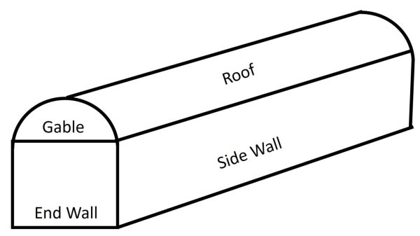
Figure 7. Greenhouse components for surface area calculation.
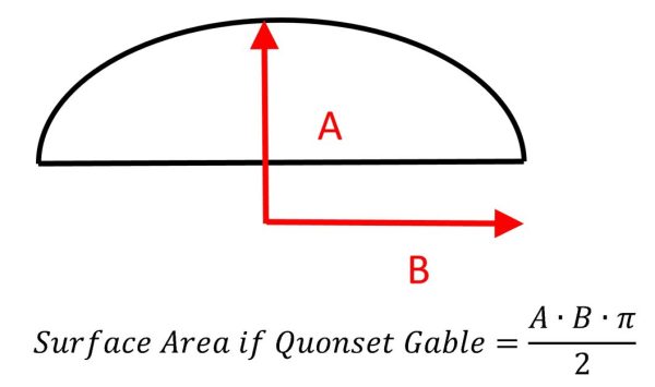
Figure 8. Formula for surface area of end wall gable.
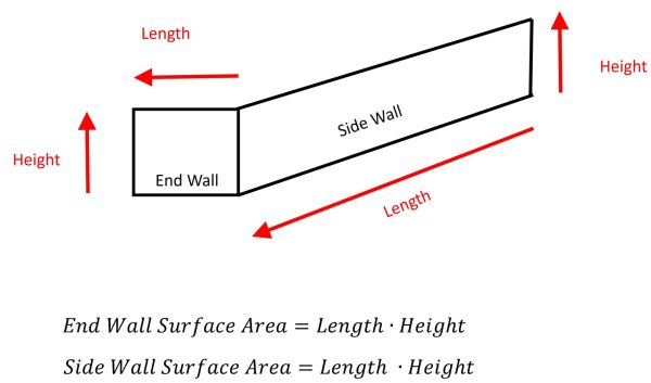
Figure 9. Formula for end wall and side wall surface area.
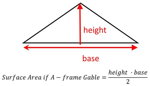
Figure 10. Formula for surface area of A-frame style gable.
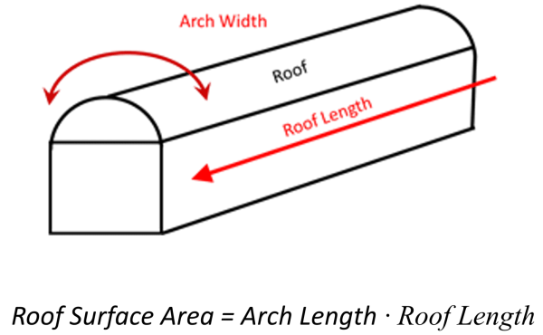
Figure 11. Formula for surface area of a Quonset-style roof.
Greenhouse Heaters
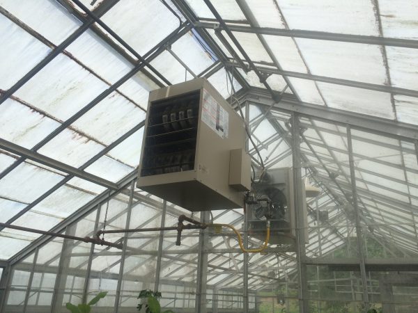
Figure 12. Forced-air gas-powered heater.
A gas-fired unit is the most common greenhouse heater used in commercial production (figure 12). Gas unit heaters can be fueled by natural gas (NG) or liquid propane (LP). Commercial growers use vented heaters where exhaust fumes are vented outside the greenhouse to prevent the accumulation of noxious gases. Super-heated exhaust fumes are channeled through a heat exchanger before being vented. To disperse heat from the heat exchanger, a high-velocity fan forces air through the heat exchanger, picking up heat and distributing it to the greenhouse air. There is a loss of efficiency due to the need to transfer heat from the fumes to the exchanger; however, nonvented heaters are less efficient in the long run. Nonvented heaters require more ventilation to reduce humidity and noxious gases, thereby lowering the overall system’s efficiency. Vented heaters are safer for employees and crops and should be used over nonvented unit heaters when possible.
Most growers in the southeast use gas-fired heaters but are always looking for more affordable ways to heat their greenhouses. Great strides have been made in solar, geothermal, and biomass fuel sources. These fuel sources have much lower costs per million BTU than LP or NG; however, equipment expenses are the most significant deterrent to their use. Before investing in alternative energy, ask the following questions:
- Reliability. Can I rely on this piece of equipment when it counts?
- Maintenance and Labor. What does it cost, and how much time does it take to reload the heater? How often will this piece of equipment require maintenance? If there is a problem with the equipment, who will be able to repair it?
- Fuel Shipping Cost. What is it going to cost to transport the fuel to my location?
- Equipment Cost. Will the long-term savings associated with an alternative energy source outweigh the initial investment in the equipment?
If using an alternative heating source, make sure a backup gas-fired heater is in place to reduce any risk associated with system failure. In some areas, most heating hours only require a fraction of the total BTU design load for a particular greenhouse. An integrated approach may allow a smaller, alternative heater with a gas-fired heater for backup. Alternative heating equipment does not have to meet the entire load capacity needed. More research is required to investigate a system approach to better greenhouse heating when using alternative heat sources.
Radiative Heat Systems
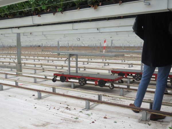
Figure 13. Radiative heat pipes used in greenhouse rail system.
Modern high-tech greenhouses may use a radiative pipe system that doubles as rails in the greenhouse walkways. These “rails” are used to roll carts and other equipment down the row middles between crops (figure 13). Radiative heat systems use water to transfer heat from a boiler system to the radiative pipes. These systems are more fuel efficient than forced-air systems. Additionally, radiative systems distribute heat uniformly through the greenhouse and below the crop, allowing the warm air to travel up through the plant canopy.
Controlling Humidity
Controlling humidity in a greenhouse is a constant challenge. As plants transpire, they release water vapor into the air. The high relative humidity creates increased disease pressure, especially if water droplets begin to accumulate on leaves. Humidity can be reduced by ventilating the greenhouse and purging humid air. Dry, cool air can be pumped with a jet fan through perforated poly tubing and evenly distributed through the greenhouse ceiling. Delivering the cool air at higher heights than the crop canopy allows the descending cool air to mix with the warm air near the crop canopy. Many growers use horizontal airflow (HAF) positioned above the crop canopy to circulate air when the exhaust fans are off (figure 4). Air movement across leaf surfaces reduces the incidence of moisture collecting on the leaves, thereby reducing disease pressure. HAF fans also keep the air in the greenhouse from stratifying by mixing warm air in the ceiling with cooler air near the plant canopy. The placement of HAF fans depends on greenhouse size. Consult the manufacturer for proper placement in your specific structure. A rule of thumb for calculating the total airflow needed is 2 cfm per square foot of greenhouse floor.
System Management & Climate Controller
Controlling the greenhouse environmental equipment can significantly influence energy and labor efficiency. Constantly having to manually open and close vents is not cost effective. Automation can significantly reduce labor costs and the stress associated with managing a greenhouse. Equipment should be properly staged for the most efficient energy use while maintaining a constant internal temperature. Numerous devices are available to control the environment. These range from a simple on/off switch to a high-tech computerized system. It is common for small growers to choose environmental control systems based solely on the price. The most widely used and inexpensive device is a common thermostat. Thermostats are not very accurate or consistent as discrepancies can occur between thermostats mounted side by side. Humidity and heat can further diminish the accuracy of thermostats over time. Position thermostats away from direct sunlight or strong air currents to represent temperatures the crop is experiencing. An aspirator box can be used to protect thermostats from false readings. Aspirator boxes have a small fan to pull air through the box and across the thermostats. Efficiency and accuracy are critical in greenhouses with equipment that must operate in stages. Special care should be made to properly calibrate each thermostat to ensure that multiple environmental controls do not unnecessarily operate simultaneously. For example, the fan and the heater should not be running simultaneously. Smart or computerized controllers offer a great deal of flexibility and can be adjusted quickly. These controllers can sometimes be monitored and adjusted from mobile phones. Smart controllers may be worth the extra expense considering their easy use and flexibility.
Mitigating Risk
It is a good idea to consider investing in an emergency call system that monitors power outages and indoor temperatures. Alarms and backup generators are essential for the conventional greenhouse grower but a must for the hydroponic grower. To mitigate risk when equipment malfunctions, some growers will purchase extra consumables such as fan belts, motors, and even extra heaters.
Growers can choose to divide their total demand load (heat or ventilation) across several smaller pieces of equipment rather than a few large ones so if one piece of equipment fails, the others may prevent a total crop loss. This approach can be done with fans or heaters. Using larger motors and heaters is more energy efficient, so careful consideration must be taken to determine risk reduction associated with smaller equipment versus long-term energy use.
Summary
When planning a greenhouse enterprise, environmental controls are typically an afterthought during the design process. The ability to regulate the environment can make or break an operation. Let an experienced engineer or consultant help you correctly design and choose the appropriate equipment.
Recommended Reading
- American Society of Agriculture and Biological Engineers. 2008. ANSI/ASAE EP406.4. Heating, Ventilating and Cooling Greenhouses. ASABE. Joseph Michigan.
- Beytes, C., 2011. Ball Red Book Volume I: Greenhouse and Equipment. 18th ed. West Chicago, Illinois: Ball Publishing.
- National Greenhouse Manufacturers Association. 2010. Heat Loss Standards.
- National Greenhouse Manufacturers Association. 2010. Ventilation and Cooling Standards.
- Wheeler, E.F., and Both, A.J. 2002. Evaluating Greenhouse Mechanical Ventilation System Performance – Part 3 of 3. Rutgers Cooperative Extension Bulletin E227.

 Jeremy Pickens, Assistant Extension Professor, Commercial Horticulture, and Daniel Wells, Associate Professor, Horticulture, both with Auburn University.
New September 2022, Controlling the Greenhouse Environment for Vegetable Crops, ANR-2925