Forestry
The importance of forest roads and consideration of their proper design is frequently neglected by forest landowners. Some forests such as wilderness areas and other forests managed on a custodial management regime do not permit or require road access. But, most forest landowners like to drive into or through their forest.
In many cases, existing roads were located and constructed many decades ago, and the landowners feel no cause for concern. But, many of these old roads are improperly located and constructed. Roads having obvious maintenance and environmental problems should be evaluated for usability and closed or relocated as necessary.
Forest roads are essential to many facets of forest management. The number of entries into a forest necessary to conduct intensive forest management activities requires that adequate forest roads be constructed and maintained. Forest roads are good fire breaks and they provide access for fire-fighting equipment. Periodic inspection for insects and disease is also facilitated by a good road system. Recreational pursuits such as hunting and camping are more easily pursued if a forest has a good road system. Intermediate and final cuttings are used by the forest manager as a silvicultural tool, and practically all methods of timber harvesting require that a system of temporary, permanent, and all-weather roads be available. Well-constructed and located forest roads are essential to modern forest management.
A cost estimate to build a forest road must include not only the initial construction cost, but also future maintenance costs. Frequently, the initial cost is the major consideration, and maintenance costs are just something to be treated in the future. Short-cutting the process of road design and location will usually mean higher future costs to the landowner. Landowners and loggers are often tempted to take the shortest route across the landscape, and they lay out roads based mainly on accessibility for logging or forest management. Roads located on terrain that is too steep are frequently gullied and eroded away. This not only creates a costly maintenance problem, but it is also an environmental concern when the eroded soil is carried as sedimentation into streams and lakes.
Moving water, such as water running downhill on a road surface, can be thought of as a source of kinetic energy. This energy is one of the primary physical causes of erosion often seen on forest roads. Kinetic energy, expressed in foot-pounds, is the energy possessed by a body because of its motion. The general mathematical formula used to calculate the amount of kinetic energy is:
Kinetic Energy = 1⁄2 (Mass × Velocity2).
The velocity of the moving water is a function of the steepness of the slope on which the road is built. Velocity contributes to the amount of kinetic energy exponentially; thus, a small increase in slope steepness rapidly increases the kinetic energy and erosive capacity of moving water. The primary means used to reduce water velocity is to locate forest roads on more gentle slopes. Alabama’s Best Management Practices guidelines call for roads to be built on slopes of 10 percent or less. But, many soils are erosive on slopes of 5 or 6 percent; therefore, a rigid guideline is difficult to prescribe.
Mass is related to the volume of water contained in the moving body of water. If the volume of water can be reduced, the kinetic energy is reduced, and thus the erosive potential of the moving body of water is reduced. We can reduce the water volume by removing the water running downhill, in and along the road, at frequent intervals. The most common method of reducing water volume in the construction of forest roads is through the use of water diversion devices. Four common water diversion devices are used:
- Water turn-outs.
- Cross-drain culverts.
- Broad-based dips.
- Water bars.
Each of these devices has specific uses and should be used appropriately. The construction costs, time, and materials vary for each device. The costs and benefits of each device should be carefully evaluated within the constraints of the specific road construction project being considered.
Water Turn-Outs
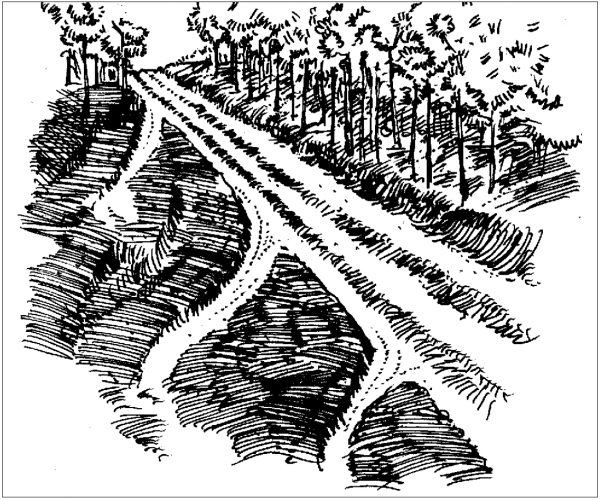
Figure 1. Water turn-outs.
Water turn-outs or wing ditches are designed to remove water from road ditches and from the downhill side of out sloped roads (Figure 1). These are the least costly of the water diversion devices, and they should be installed during the construction of the “roughed-in” or pioneer road. The water turnout should be graded on a 2 to 3 percent slope to allow constant drainage, which will flush most sediment out of the turn-out. As the turnout is usually built with a crawler tractor, the operator must be sure that the spoil from the turn-out construction is scattered and not allowed to form a dam at the end of the turn-out. This will allow the outlet drainage to be dispersed into nearby forest vegetation, which will filter the sediment out of the discharge water. Best Management Practices also require that you exercise extra caution to avoid discharging water from a turn-out directly into a stream; this discharge should flow through a streamside management zone before entering a stream or other water body.
Cross-Drain Culverts
Cross-drain or ditch relief culverts are used on crowned or ditched roads (Figure 2), and are probably the most expensive of the four water diversion devices. The purpose of these devices is to move water under the road from the uphill ditch before the flow gains sufficient volume to erode the ditch. Placing the culvert on a 2 to 4 percent grade—and at a 30-degree angle downgrade across the road to allow smooth entrance of water at the inlet—will help make the culvert self-cleaning of sediment. To be sure that no water by-passes the inlet, install a control backstop of earth, rip-rap, sandbags, or half-culvert sections on the downhill level of the inlet.
Size the cross-drain culvert adequately to handle the maximum water volume expected. An 18-inch minimum diameter is recommended, with at least one-half the culvert diameter—but not less than 12-inches—of fill over the top of the culvert. Extend the cross-drain culvert length 1 to 2 feet past any fill and place an energy dissipator, such as brush or rip-rap, at the outlet end of the culvert to minimize erosion.
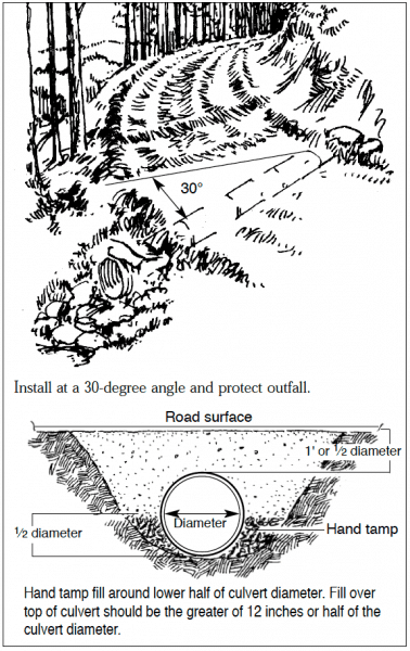
Figure 2. Cross-drain culvert installation.
Broad Based Dips
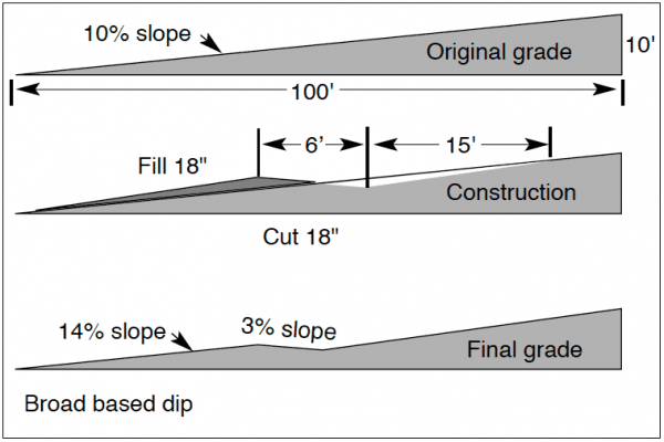
Figure 3. Broad based dip construction. Cut to an approximate depth of 18 inches and back-ill with #1 & #4 crushed rock for smooth travel surface.
Broad based dips (Figure 3) are an alternative method to cross drain culverts to remove water across and off a forest road. Broad based dips work best on outsloped roads and on road grades of less than 10 percent. The construction of a broad based dip involves a road section of 15 to 75 feet in length that is dropped at an approximate 3 percent reverse grade, approximately 12 to 18 inches below grade, and then raised back to the original grade. The specification for broad based dip construction is dependent on the designed grade of the road surface (Table 1). The lowest portion of the dip should be constructed at a 3 percent outslope to facilitate drainage, and the dip should be surfaced with crushed rock to minimize erosion and rutting by vehicular traffic during wet weather. When constructing the dip, make certain that the outlet, much like a water turn-out, is at the lowest point of the dip.
Broad based dips are not well liked by loggers because of the twisting effect on the frame of a loaded log truck. Overcome this disadvantage by back-filling the lower 15 inches of the dip with large (#1: 3- to 4-inch screen) crushed rock; then overlay with smaller (#4: 1- to 2-inch screen) crushed rock to bring the level of the dip back to the original road surface elevation. The rock allows water to infiltrate through the dip, while allowing a level surface to facilitate normal vehicular speed over the dip.
Table 1. Example Specifications For A Broad Based Dip Backfilled With Crushed Rock.
| Designed Grade (%) | Approach Distance (ft.) | Exit Grade (%) | Exit Distance (Ft.) |
|---|---|---|---|
| 2 | 75 | 3 | 15 |
| 3 | 50 | 3 | 13 |
| 4 | 38 | 3 | 11 |
| 5 | 30 | 3 | 10 |
| 6 | 25 | 3 | 9 |
| 7 | 22 | 3 | 8 |
| 8 | 19 | 3 | 7 |
| 9 | 17 | 3 | 7 |
| 10 | 15 | 3 | 6 |
| 11 | 14 | 3 | 4 |
| 12 | 13 | 3 | 3 |
| 13 | 12 | 3 | 3 |
Water Bars
Water bars are used primarily when a road will be put out of use for an extended period of time. Vehicular traffic should be minimized and the water bars should be seeded and fertilized to reduce erosion. A water bar is constructed by excavating a trough 2 feet deep by 4 feet wide at a 30-degree angle across the road. The excavated earth should be piled on the downhill side of the water bar. To be sure that no water by-passes the water bar, the uphill end of the water bar should be connected to the upper bank of the road. A properly constructed water bar also has an outlet on its downhill end to allow water to be directed into the nearby forest vegetation.
Although water bars are recommended for inactive roads, some landowners use a smaller, modified version of a water bar in conjunction with a water turn-out on active roads. These combination devices are adequate for light vehicular (pick-up truck) traffic; but, they will wear down quickly if they become rutted during wet weather usage.
Spacing Between Water Diversion Devices
The appropriate spacing between water diversion devices depends on the steepness of the road grade and the erosivity of the soil. The steeper the grade, the greater the velocity of the water body, and the closer water diversion devices must be placed together. Spacing tables have been developed for these devices (Tables 2 and 3). But, if you are in the woods and don’t have a table handy, a common rule of thumb for spacing of turn-out, broad based dips, and cross-drain culverts is:
Spacing between devices
(in feet) = (400 / slope %) + 100.
Example: Slope of road = 8%
Spacing between devices = (400 / 8) + 100 = 150 ft.
Table 2. Suggested Distances Between Culverts, Water Turnouts, And Broad Based Dips On Forest Roads.
| Road Grade (Percent) | Distance (Feet) |
|---|---|
| 2 | 300 |
| 4 | 175 |
| 6 | 125 |
| 10 | 80 |
Table 3. Recommended Distances Between Water Bars On Skid Trails And Logging Roads After Logging Is Complete.
| Road Grade | Spacing (Feet) |
|---|---|
| 2 | 250 |
| 5 | 135 |
| 10 | 50 |
| 15 | 60 |
| 20 | 45 |
| 25 | 40 |
| 30 | 35 |
| 40 | 30 |
Conclusion
Water diversion devices are an often neglected component of forest road construction. When properly constructed and used at appropriate intervals, these devices can greatly reduce road maintenance costs, erosion, and sedimentation of our streams. When you construct your next forest road, include an adequate number and type of water diversion devices. You will be a better steward of the land, have greater accessibility to your forests, and save money in the future.
Richard W. Brinker, former Extension Specialist, Dean Emeritus & Professor, Forestry and Wildlife Sciences, Auburn University. Robert Tufts, former Extension Specialist & Professor, Forestry and Wildlife Sciences, Auburn University.
Reviewed May 2022, Forest Roads and Construction of Associated Water Diversion Devices, ANR-0916