Forestry

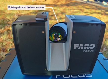
Figure 1. The scanner head of the FARO Focus Premium terrestrial laser scanner showing the rotating mirror of the sensor. This scanner has a maximum range of 0.22 miles (350 meters).
Terrestrial laser scanning (TLS) is a novel technology that enhances the monitoring of urban trees. This technology creates detailed three-dimensional images of trees using laser pulses, allowing scientists and forest managers to collect precise tree measurements. In this publication, the principles of TLS technology are explained, and some important considerations for collecting tree scans are given. Written for natural resource management professionals and the general public, the information provided here offers practical knowledge about this novel technology, focusing on urban trees.
What is a terrestrial laser scanner?
A terrestrial laser scanner (TLS) is a ground-based active remote sensing technology that uses LiDAR (light detection and ranging) to create detailed three-dimensional images of surrounding objects. Unlike passive remote sensors such as aircraft cameras that rely on natural light, LiDAR works by creating and emitting laser pulses that bounce back to the scanner after hitting on the surface of structures such as vegetation, buildings, or terrain features, recording millions of three-dimensional points of the surrounding scene, which is called a point cloud. This technology has proven highly effective in quantifying the aboveground architecture of trees.
What is a point cloud and how is it created?
TLS consists of a laser sensor that emits millions of laser pulses, which backscatter when they hit an object and are recorded by the scanner head. These pulses are distributed around by rotating mirrors (figure 1), allowing the scanner to capture the scene. As a result, the scanner captures millions of laser points that represent the surrounding environment, creating a point cloud (figure 2). These points also have color information. A built-in camera inside the scanner records the color information of each point. A point cloud has X, Y, and Z coordinates and red, green, and blue (RGB) color information.

Figure 2. The three-dimensional laser point cloud of a southern red oak tree (Quercus falcata) is displayed here in two dimensions. A small area of the point cloud has been zoomed in to visualize the laser points better. Each point has unique X, Y, and Z coordinates and RGB color values.
Components of a Terrestrial Laser Scanner
The terrestrial laser scanner has two basic parts: the scanner head and the tripod (figure 3). The scanner head consists of a laser sensor and a built-in camera. In addition to the laser sensor, there are a few more internal sensors, such as the inclinometer, the compass, the altimeter, and the GPS. Integrating multiple sensors in a TLS is crucial to ensure accurate data acquisition.
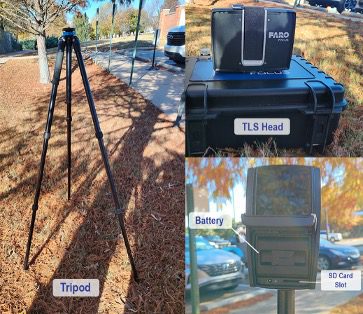
Figure 3. Different parts of a terrestrial laser scanner
The built-in inclinometer is used to level the scanner properly (figure 4), which is important because it affects the accuracy of measurements in different directions. When the scanner is not leveled, it introduces systematic errors in distance and angle measurements that propagate through the entire dataset. The adjustable legs of the tripod can also be used to level the scanner on uneven terrain.
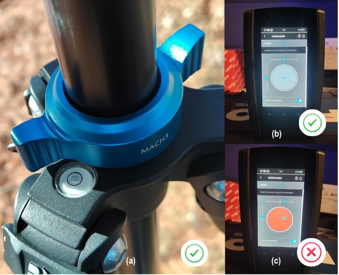
Figure 4. (a) Properly leveled scanner as shown by the bubble leveling system of the tripod; (b) Properly leveled scanner as indicated by the internal inclinometer sensor; (c) Unleveled scanner with a warning displayed by the internal inclinometer sensor.
TLS produces laser pulses with energy the built-in battery provides, which requires careful attention. For example, the battery of the Faro Focus Premium laser scanner (figure 5) lasts approximately 4 hours of continuous use. Additional batteries are recommended to ensure uninterrupted data collection in the field.
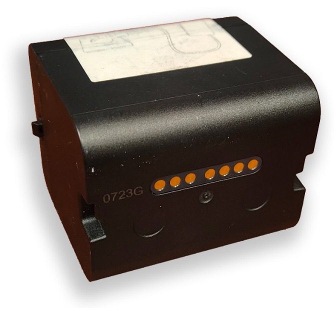
Figure 5. Battery of the Faro Focus Premium terrestrial laser scanner.
Important Considerations Before Laser Scanning Trees
Before conducting any scans, one must carefully consider the weather conditions as the scanner has sensitive sensors that must be protected from moisture. Scanning on days with rain, dense moisture, or during snowfall must be avoided. Similarly, wind conditions must be considered. Strong wind gusts can cause excessive sway of stems and branches, which should be avoided during laser scanning. This sway creates a ghost effect, noise in the point cloud where a single branch or stem may appear at multiple positions. This results in biased estimates of tree structure (figure 6). To minimize the effect caused by wind, scanning should only be done when the wind speed is significantly less than 1 meter per second.
Optimal scan resolution must be determined before laser scanning, as it directly affects the final point cloud quality. Scan resolution is one of the factors affecting point cloud density, meaning how closely individual laser points are spaced. Higher resolution results in more points being captured per unit area, providing a more detailed representation of the scanned object or environment. Scan quality relates to the precision and clarity of the captured data points, and it is influenced by both the scanner’s technical characteristics and environmental conditions during the scanning process (e.g., wind). While increasing resolution can significantly enhance the detail and accuracy of the point cloud data, this comes with longer scanning times and larger data file sizes. Adopting appropriate standards for scanning resolution and quality is necessary. The standards depend on the required level of detail and other logistical factors (e.g., available time for data collection, data storage, data processing capability, budget constraints).
Finally, all the equipment should be regularly inspected before going to the field. Specifically, batteries must be fully charged, the scanner’s internal memory must have sufficient storage space, and all the sensors must be calibrated in a timely manner.
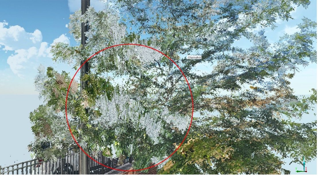
Figure 6. Ghost effect (noise) highlighted in a bald cypress (Taxodium distichum) tree point cloud
Laser Scanning Trees
Trees must be scanned from multiple positions to create a complete point cloud. This is primarily due to the occlusion problem, when parts of a tree (e.g., branches, foliage) block the scanner’s view to areas behind them, creating gaps in the point cloud. Occlusion occurs because laser pulses cannot penetrate and see inside an object. For example, when scanning a tree from one side only, the trunk may block the scanner’s view of branches on the opposite side, while dense foliage can prevent capturing branches and structural elements behind them.
To overcome this problem, we capture multiple scans from different distances and directions around the trees. Some level of occlusion will always exist in the point cloud, but it should be reduced as much as possible. If the tree of interest is an open-grown street tree, scanning from four locations around a tree (north, south, east, and west) helps to capture the full circumference of the trunk and major branches. Additional scans at different angles and distances closer to the tree can provide a more detailed view of the upper canopy. Four to six scan locations spaced at regular intervals and positioned at different angles are necessary to scan an individual tree. Depending on the tree size, these locations are between 3.3 and 49.2 feet (1 and 15 meters) from the tree base (figure 7).
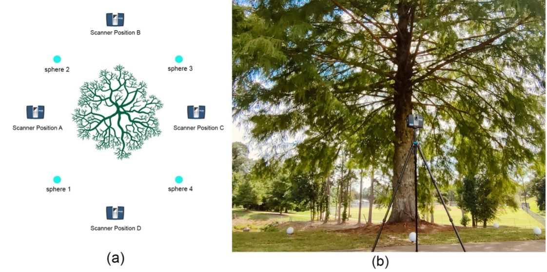
Figure 7 (a) Scanning layout for an individual tree showing the scanner positions and the location of the target spheres. (b) In this actual field data collection, the Faro Focus Premium terrestrial laser scanner scans a bald cypress (Taxodium distichum), and white target spheres are placed on the ground around the tree.
A systematic grid-based approach is needed to scan groups of trees, such as an urban forest stand (figure 8). The scan locations should be placed on a grid, with spacing that depends on vegetation density. A 32.8 x 32.8 foot (10 x 10 meter) grid works well for dense urban forest patches, whereas a 65.6 x 65.6 foot (20 x 20 meter) grid is more suitable for relatively open urban forest areas.
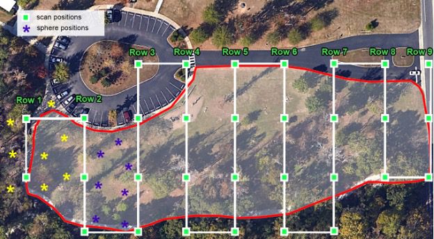
Figure 8. A 65.6 x 65.6 foot (20 x 20 meter) grid for scanning a group of trees within the red-circled area. The scanning positions are marked with green rectangles, while the sphere target positions are indicated with asterisks of different colors for each row. Sphere targets are displayed here on a row basis and are moved to the next row after a row has been scanned. Scanning begins from one side and follows a sequential path to the other side.
The scans taken from multiple positions need to be merged to create a complete single three-dimensional point cloud. To merge multiple scans, some common objects that can be identified by the computer algorithms used to process the data need to be in the scene. This process is called co-registration. The most common type of objects used in the field are retroreflective spherical targets (figure 9b). The software used to co-register the multiple scans automatically detects these identical spheres, making the process fully automated. There are also other types of targets, such as checkerboard targets (figure 9a). To accurately merge laser scans, at least four common reference targets must be visible at the consecutive scan positions.
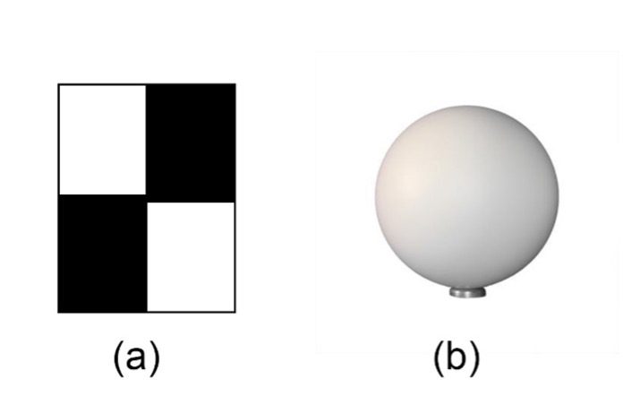
Figure 9. (a) checkerboard target (b) retroreflective spherical target
Step-by-Step Scanning Process
Step 1: Walk around the scanning area to assess the environment and focus on the trees of interest and any objects that can potentially interfere with the laser scanning.
Step 2: Determine the appropriate number of laser scans and the laser scanning locations needed to capture complete point clouds of the trees of interest to minimize occlusion.
Step 3: Place spheres or other reference targets around the trees of interest, and make sure that these reference targets are visible in all scans.
Step 4: Mount the laser scanner head on the tripod and turn it on. Then ensure it is leveled and check all important sensors (e.g., internal inclinometer, compass, camera, etc.).
Step 5: Determine the laser scanning parameters (resolution, quality, color capture) and begin to scan.
Conclusion
TLS is a powerful tool for creating detailed threedimensional representations of trees, providing valuable data for urban forest monitoring and management. Proper preparation, such as ensuring the equipment functions properly, selecting the optimal scanning resolution, and laying out the scanning positions, is essential to ensure high-quality data collection. Minimizing occlusion is particularly important as it directly affects the accuracy of tree structure measurements. TLS technology is continuously growing with several applications in urban forestry and arboriculture, offering new insights into tree architecture and improving our ability to quantify the benefits of urban forests.
Additional Resources
Visit https://skfb.ly/p8GKY to see the three-dimensional point cloud of a southern red oak that was scanned using the FARO Focus Premium terrestrial laser scanner on the Auburn University campus.
Visit https://youtu.be/7SzsJ5a7Ips to watch a plot level point cloud animation video.
Suggested Literature
- Arseniou, G., MacFarlane, D. W., Calders, K., & Baker, M. (2023). Accuracy differences in aboveground woody biomass estimation with terrestrial laser scanning for trees in urban and rural forests and different leaf conditions. Trees – Structure and Function, 37(3), 761–779.
- Calders, K., Adams, J., Armston, J., Bartholomeus, H., Bauwens, S., Bentley, L. P., Chave, J., Danson, F. M., Demol, M., Disney, M., Gaulton, R., Krishna Moorthy, S. M., Levick, S. R., Saarinen, N., Schaaf, C., Stovall, A., Terryn, L., Wilkes, P., & Verbeeck, H. (2020). Terrestrial laser scanning in forest ecology: Expanding the horizon. Remote Sensing of Environment, 251, 112102.
- Wilkes, P., Lau, A., Disney, M., Calders, K., Burt, A., Gonzalez de Tanago, J., Bartholomeus, H., Brede, B., & Herold, M. (2017). Data acquisition considerations for Terrestrial Laser Scanning of forest plots. Remote Sensing of Environment, 196, 140–153.
 Samit Kafle, Graduate Research Assistant, and Georgios Arseniou, Extension Specialist, Assistant Professor, both with Forestry and Wildlife Sciences, Auburn University.
New June 2025, Urban Forest Monitoring with Terrestrial Laser Scanning, FOR-2180

