Fish & Water
This is an excerpt from “Pond Building: A Guide to Planning, Constructing & Maintaining Recreational Ponds,” ANR-1114. Find all sections of the publication at www.aces.edu.
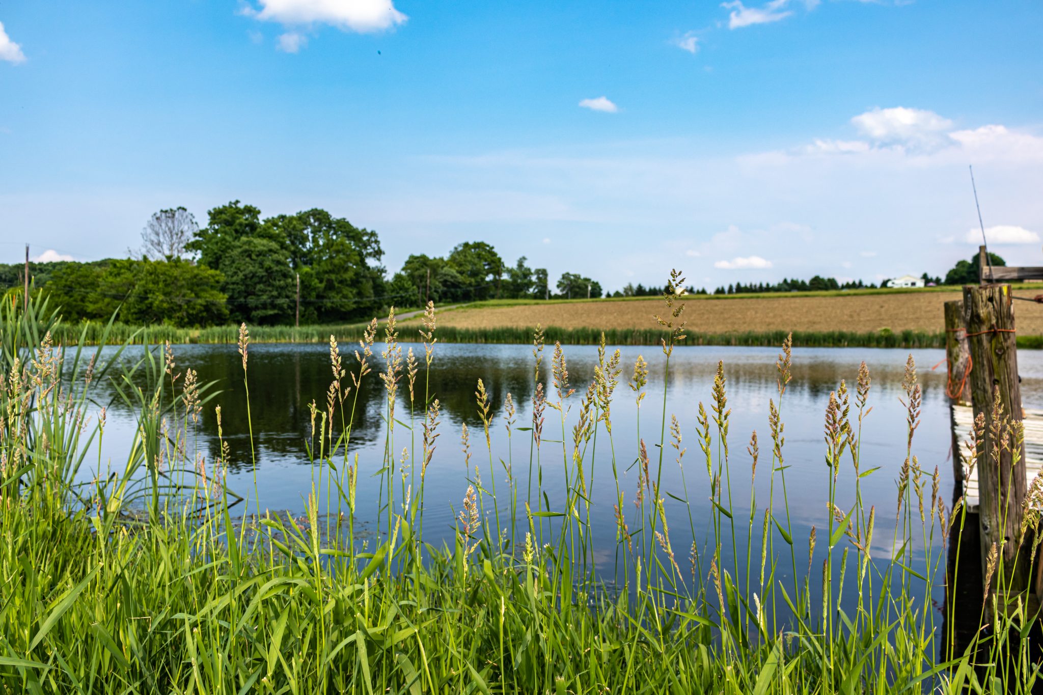
Water adds variety to a landscape and further enhances its quality. Reflections in water attract the eye and help create contrast or a focal point in the landscape. A pond visible from a home, patio, or entrance road increases the attractiveness of the landscape and often improves land value. Good landscape design techniques include consideration of size, site visibility, relationship to the surrounding landscape and use patterns, and shoreline configuration.
Where possible, locate the pond (or house) so that the major sight line crosses the longest dimension of water surface. You want a viewer to see the water first before noticing the dam, pipe inlet, or spillway. Minor changes in the dam alignment and spillway location can shift these elements out of view and reduce their prominence.
When feasible, locate the pond so that some existing trees and shrubs remain along part of the shoreline. Shoreline trees and shrubs add interest by casting reflections on the water, providing shade on summer days, and helping blend the pond into the surrounding landscape. A pond completely surrounded by trees, however, will appear smaller than a pond the same size without trees or with few trees.
Trees completely surrounding a small pond can drop an excessive amount of leaf litter into the pond. While some leaf input is not a problem, and could be positive by increasing insect food for the fish, excessive leaves can cause the water to have a brown tannin stain color, cause a thick mucky buildup in the bottom, and generally reduce overall productivity of the pond. Ponds constructed in woods should have the cleared limits irregularly shaped to provide a natural-appearing edge and open area.
Never plant trees on the dam, other levees, or along the emergency spillways. Tree roots can cause seepage, and a falling tree can create holes in these structures that cause the catastrophic failure of the dam.
Further transition with vegetated surroundings can be accomplished by feathering clearing edges. Density and height of vegetation can be increased progressively from the water’s edge to the undisturbed vegetation. The shape of a pond should complement its surroundings. Irregular shapes with smooth, flowing shorelines are generally more compatible with the lines of countryside landscapes.
Types of Ponds
EMBANKMENT PONDS
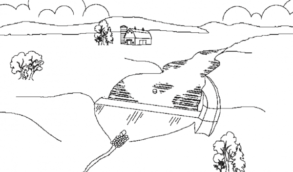
Figure 2. Embankment pond (not to scale)
The most common type of pond in Alabama is the embankment pond, also called watershed pond or hill pond (figure 2). A watershed is the drainage area around the pond within which rainfall drains toward the pond. A dam or embankment is constructed in a depression between two hills and serves to impound water in a basin area on the upstream side of the dam. This type of pond is best suited for areas with slightly to moderately rolling topography.
Embankment ponds usually depend on rainfall runoff to fill and then maintain water levels. Pond size, shape, and depth are limited by the topography of the site and the size of the watershed draining to the pond. Generally, the steeper the slope of the pond site, the smaller the pond that can be constructed.
Well-sited embankment ponds generally require the least amount of earth moving per acre of water impounded compared to other types of ponds. Because construction costs are based largely on the amount of earth being moved, an embankment pond is generally the least expensive type of pond per surface acre of water to construct.
Building a dam across a large, permanent stream is not a recommended practice for constructing a pond. Following heavy rainfall, streams often carry large amounts of suspended sediments that settle out in the pond and severely shorten its useful life. Ponds fed by large streams can be difficult to manage for fishing because of competition from wild fish, the introduction of fish diseases, and the inability to effectively fertilize the pond because of excessive outflow.
EXCAVATED PONDS
Excavated, or dug, ponds are constructed almost entirely below the original ground level (figure 3). This construction method is usually used only for construction of small ponds (generally less than 1/2 acre) because of the large amount of earth moving required in relation to the size of the pond. Excavated ponds may require an external water source to fill and maintain if springs, groundwater, or runoff are not sufficient. An excavated pond is usually the most expensive type of pond to construct on a per-acre basis.
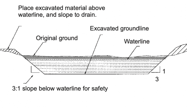
Figure 3. Typical section of an excavated pond (not to scale)
LEVEE PONDS
Suitable for flat or nearly flat land, levee ponds are only partially excavated. Earth from what is to be the basin area of the pond is removed and used to construct the sides, or levees, of the pond that impound the water (figure 4). The water level in a levee pond is higher than the original ground level. Water depth is usually similar throughout the pond and is regulated by the height of the outlet pipes and constructed levees. An externally pumped water source, such as a well or creek, will be necessary to fill and maintain this type of pond because of the absence of a watershed. Per-acre construction costs of levee ponds generally fall between those of watershed and excavated ponds.
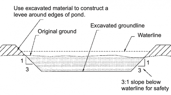
Figure 4. Typical section of a levee pond (not to scale)
COMBINATION WATERSHED-LEVEE PONDS
An example of a combination watershed-levee pond would be a two- or three-sided levee pond that connects to an existing hill to form its other side (figure 5). Depending on the site, the hill side of the pond can provide a significant amount of watershed runoff to the pond, thus reducing and, in some cases, eliminating the need for pumping water to fill and maintain the pond.
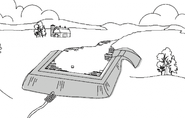
Figure 5. Combination watershed-levee pond (not to scale)
Pond Design and Layout
TECHNICAL ASSISTANCE
Proper construction of a pond must be preceded by proper planning and design. The major considerations to be determined in planning and designing a pond are the size and shape of the pond and the water control structures required.
The Natural Resources Conservation Service (NRCS) can provide advice and information to help private landowners wishing to construct a pond. The NRCS provides guidance for wetland determination, soil maps, uses of ponds for farm needs, and basic design consideration. Local NRCS office contacts can be found at https://offices.sc.egov.usda.gov/locator/app?agency=nrcs. Private consultants (professional engineers) are available for a fee to provide more detailed planning and land surveys.
POND DEPTH AND VOLUME
To ensure a permanent water supply, the water in the pond must be deep enough to meet the intended use requirements and to offset probable seepage and evaporation losses. Ponds should have a minimum average depth of 6 to 8 feet with water at least 4 feet in depth at an easily fishable distance from the shore. Greater minimum depths are needed for ponds in which a permanent or year-round water supply is essential, such as for irrigation or firefighting, or where seepage is more than normal. Most typical farm ponds in Alabama have 10 to 15 feet of water at the dam.
The estimated capacity, or volume, of the pond can be determined by multiplying the surface area of the pond in acres by 0.4 times the maximum water depth in feet measured at the dam. For example, a pond with a surface area of 3.2 acres and a depth of 12.5 feet at the dam has an approximate capacity of 16 acre-feet (0.4 × 3.2 × 12.5 = 16 acre-feet; 1 acre-foot = 325,851 gallons). An exact capacity of the pond can be obtained only through detailed surveys and calculations.
Ponds should have a minimum average depth of 6 to 8 feet with water at least 4 feet in depth at an easily fishable distance from the shore. For more information on managing ponds for fishing, see “Management of Recreational Fish Ponds in Alabama” (Extension publication ANR-0577).
Tip to Remember
Fish are stocked based on pond surface acreage, not depth. A pond that maintains an average depth of 15 feet produces no more fish than a pond maintaining a 6-foot average depth.
WATER CONTROL STRUCTURES
There are two water control structures (spillways) that must be designed and sized appropriately to make sure that water can safely drain from the pond during routine and heavy rainfall events. The primary spillway is usually a pipe system (standpipe, siphon system, or a pipe at the waterline through the top of the dam) that is sized to carry all but the very heaviest rainfall. The emergency spillway is normally a lower section of the dam with an open channel designed to carry the water around and away from the base of the dam during high water events. Predicted large storm events, the slope of the watershed, the type of vegetation, and soils all play a role in the design of a safe dam; this includes the top- of-dam elevation and adequate freeboard, which is the distance between the designed flow of the emergency spillway and the top of the dam, usually about 1 foot (figure 6).
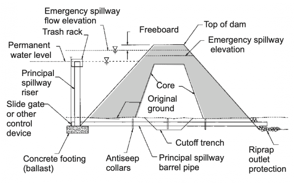
Figure 6. Typical cross section of dam along centerline of principal spillway (not to scale)
Principal Spillway
The principal spillway through the dam designed to control runoff from routine rainfall has several key components. The most common design is a standpipe with a barrel through the base of the dam. This system has the advantage of allowing control of the water height for repair or complete restoration by opening a valve at the bottom of the standpipe. Previously, NRCS recommended installing an antiseep collar around the barrel to ensure that water from the pond does not leak between the outside surface of the barrel pipe and the earthfill of the dam (figure 7).
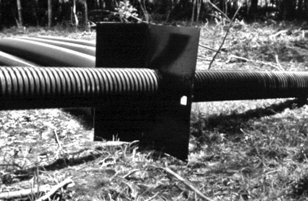
Figure 7. While we recommend smooth steel, PVC, or aluminum for the barrel through the dam and not the corrugated pipe shown here, this picture shows the antiseep collar designed to reduce leakage around the pipe.
Achieving good compaction of the earthfill around the barrel pipe is extremely important. This area is often the weakest portion of the earthfill and where many dams develop leaks. The current recommendation of NRCS as an alternative to antiseep collars is a filter and drainage diaphragm that can be installed around the barrel pipe (figure 8). This system collects seepage and channels it through the dam without eroding the area around the barrel pipe. Contact your local NRCS office for detailed information on the design and installation of a filter and diaphragm seepage control system.
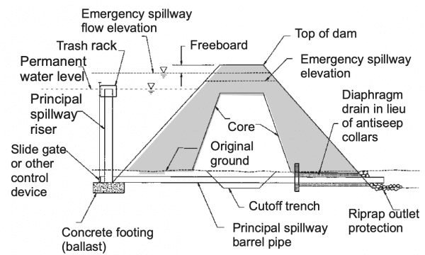
Figure 8. Typical cross section of dam along centerline of principal pillway (not to scale)
The vertical pipe attached to the barrel pipe at the upstream side of the dam is called the riser (figure 9). The riser pipe must be adequately sized to deliver water to the barrel pipe and is usually one and a half to two pipe sizes larger than the barrel pipe.
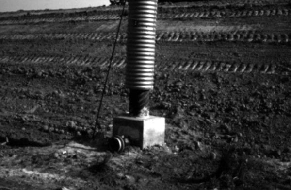
Figure 9. Principal spillway showing barrel pipe connected to riser pipe with concrete counterweight attached to base of riser to counteract buoyancy
A trash rack must be placed on the riser pipe to keep floating debris from clogging the pipe system. A sleeve- type trash rack can be used for deepwater release to help improve the pond water quality. Keep in mind that the riser pipe has a tendency to float. Attach a concrete counterweight of the appropriate size to the base of the riser to counteract buoyancy.
As an alternative to the conventional barrel and riser principal spillway system, a siphon pipe spillway can be used (figure 10). Consider the siphon for older ponds that are being renovated and require a new principal spillway system.
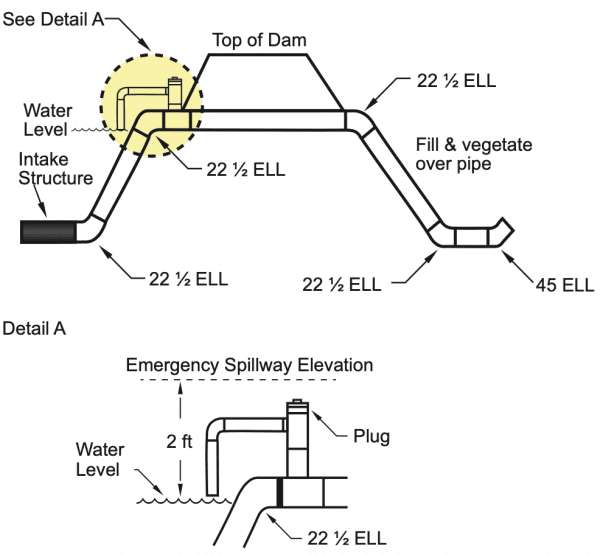
Figure 10. Siphon system. Outlet should be 4 feet lower than intake structure.
The siphon spillway is formed in the shape of an inverted V over the dam and positioned so that the crest of the siphon is at the normal water surface elevation. Siphoning action begins when the air in the siphon tube has been exhausted. An air vent is provided to break the siphon action when the pond surface is drawn down to the normal water surface elevation.
The siphon system must be periodically checked and maintained since a plugged air vent could cause the pond to drain. The system can be designed with a simple open vent so that a siphon never forms unless the vent is closed with a valve to permit lowering the water for maintenance.
While the siphon system has the advantage of not having a barrel through the bottom of the dam, the disadvantage is that the pond cannot be completely drained and maintained dry by opening a valve. Once the siphon is broken when the pond is lowered, the pond begins to refill.
The principal spillway pipe system should be constructed of smooth steel or PVC piping. Aluminum pipe can be used, but it is typically too expensive for most recreational pond applications. If PVC is used and exposed to sunlight, it should be painted to prevent degradation due to ultraviolet light.
Emergency Spillway
The emergency spillway for the pond is designed to safely carry runoff from larger storms around the dam (see figure 2). The spillway is generally located on one end of the dam in undisturbed soil. It should be well vegetated with grass to reduce erosion, and no trees or shrubs should be planted or allowed to grow in it.
The spillway should be kept clear of structures. Should fencing be necessary to control livestock through the spillway, it must be routinely cleaned to prevent the buildup of debris.
The only structure recommended to build across the spillway is a grass carp barrier to help retain fish in the pond during high water events (figure 11).
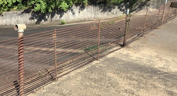
Figure 11. See “Using Grass Carp to Control Weeds in Alabama Ponds” (Extension publication ANR-0452) for design of a grass carp barrier.
Sizing Water Control Structures
Typical barrel pipe sizes range from 4 to 30 inches in diameter, and riser pipes range from 6 to 48 inches in diameter. Emergency spillways can be anywhere from 10 to 50 feet wide or wider. The actual size of the principal spillway pipes and the emergency spillway width and elevation should be determined using approved design techniques and by qualified individuals. Improperly designed spillways could create an unsafe dam and place undue liability on the owner.
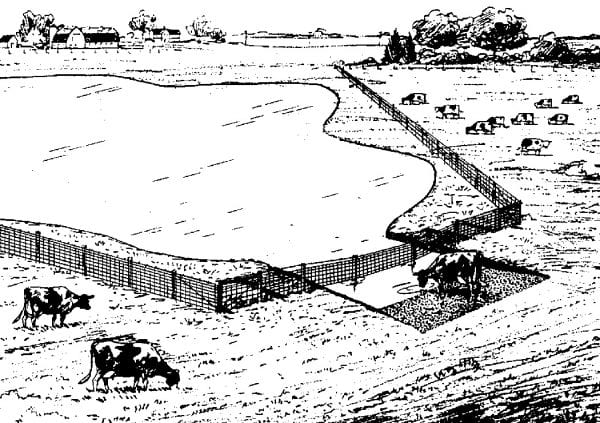
Figure 12. Livestock watering with limited access to watering ramp
Livestock Watering Access
Water from a pond is often used as a primary source of drinking water for livestock. However, the practice of allowing cattle unrestricted access to a pond has detrimental effects on the pond water quality, the health of the cattle, and the vegetative cover on the dam and shoreline. Cattle should be fenced out of the pond and off the dam.
Limited access for cattle at a planned location (watering ramp) can be provided; however, the best alternative is to fence cattle entirely out of the pond and provide water by gravity flow or pump into a trough or tank.
If a watering ramp is provided, give cattle access to the pond only at the ramp location with a walking surface protected with geotextile filter fabric covered with crushed stone (figure 12). This allows the cattle access to the pond without miring in mud to get to the water. Eliminate any potential shade around the watering ramp to keep cattle from loafing in or near the pond.
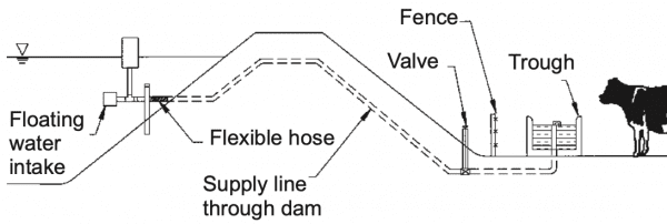
Figure 13. Livestock watering with no access to pond (not to scale)
A watering trough below a fenced pond has proven to be one of the best livestock watering systems (figure 13). A trough or tank is placed downstream of the dam and connected to the pond water by a 1 1/2-inch plastic pipe. The intake in the pond has a strainer and is located to ensure a supply of water during drought conditions. The outlet in the trough is equipped with a valve to control the water supply. The area around the trough is protected from erosion using either concrete or geotextile filter fabric and crushed stone.
If water cannot be supplied by gravity feed, a small pump may be needed to supply water to the system. These pumps can be electrical with power supplied from the power grid or remotely with solar panels. The water also can be pumped mechanically using windmills or a pasture pump where power is provided by the livestock pushing a diaphragm with their muzzles.
 Revised by Russell Wright, Extension Fisheries Specialist, School of Fisheries, Aquaculture, and Aquatic Sciences, Auburn University. Written by Chris Hyde, Extension Aquaculturist, Department of Fisheries and Allied Aquacultures, Auburn University, and Perry Oakes, State Conservation Engineer, USDA Natural Resources Conservation Service, Alabama. Adapted from “Ponds–Planning, Design, Construction,” USDA NRCS. 2000. Agricultural Handbook Number 590.Washington, D.C.
Revised August 2023, Pond Building: A Guide to Planning, Constructing & Maintaining Recreational Ponds, ANR-1114