Farming
Electrical motors are an integral part of a poultry farm operation. They drive ventilation fans, heater blowers, stir fans, feed bin and feed line augers, lift systems for feed and water lines, and actuators for tunnel and vent doors. A two-house (66 × 600 feet each) poultry farm, for example, has over 80 electric motors comprised of 48 fan motors, 16 feed line auger motors, 4 feed fill auger motors, 4 tunnel door/curtain machine motors, 4 vent machine motors, and others.
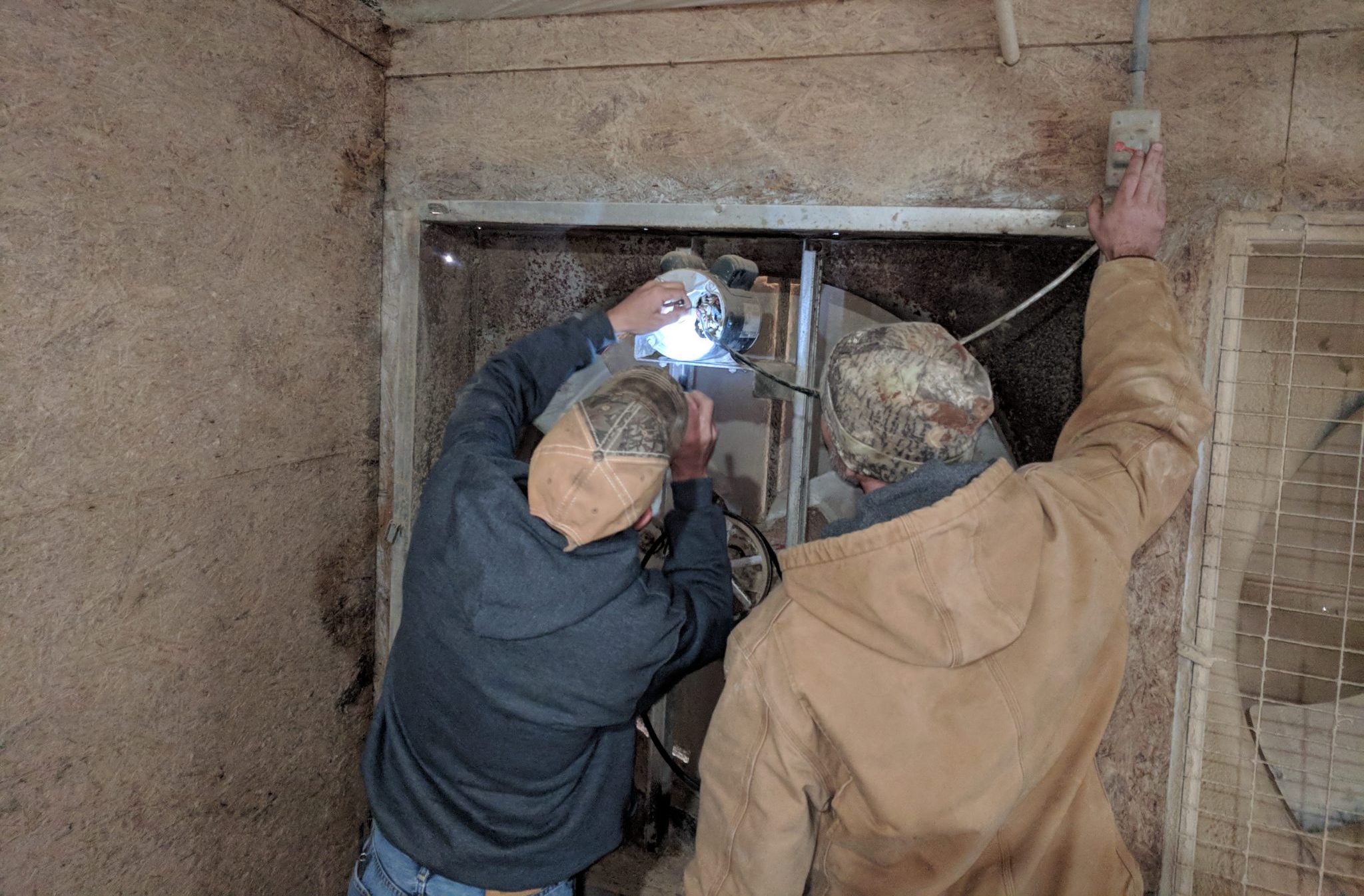
We see and hear of the challenges producers face in swapping out electric motors (figure 1) when they “go bad” and stop working. The cost of replacing a farm motor can range between $200 and $500-plus depending on the type of motor, size, and brand name. The motor can take 1 to 2 hours to replace depending on how easy it is to remove attached equipment, such as pulleys and shafts, and rewire and attach the new motor.
Oftentimes it is not the motor that has gone bad but a motor capacitor that has failed. Motor capacitors cost between $10 and $20 depending on the capacitor use, size, and brand name. A capacitor can be checked and replaced in 20 minutes if the producer has the replacement on hand, a few tools, and the knowledge to safely troubleshoot.
-
- Figure 1. A broiler producer replacing a 1 horsepower (hp) electric motor on a tunnel ventilation fan
-
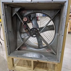
- Figure 2. A 36-inch galvanized fan with cone demonstration unit. The fan has a 1⁄2 hp motor with a switch on the start capacitor to demonstrate a “working” capacitor and a “dead” capacitor. Fan shutters removed for clarity.
Purpose of Motor Capacitors
Single-phase alternating current (AC) motors are designed to carry a given load but need an extra boost to get and sometimes keep the load moving. A motor capacitor is an electrical storage unit that stores and releases energy to increase the current to one or more copper windings of a single-phase motor to create this extra boost and increase the motor torque.
Figure 2 shows a 36-inch galvanized fan with cone that we use to demonstrate motor capacitors at the National Poultry Technology Center (NPTC). A switch on the start capacitor allows us to demonstrate a “working” capacitor and a “dead” capacitor. This shows the value of a start capacitor and why producers should care that it is working.
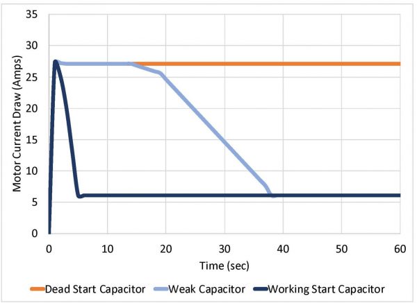
Figure 3. Graph of current draw from a 1⁄2 hp fan motor (wired for 120 volts) using working, weak, and dead capacitors over a 60-second period.
Figure 3 is a graph of current draw from the 1⁄2 hp fan motor over a 1-minute period using working, dead, and weak start capacitors. The fan with a working start capacitor uses a short spike in current draw (27.2 amps at 120 volts) to spin the fan up quickly and then drop to an operating current of 6.1 amps.
The fan with a dead start capacitor immediately begins and continues to draw 27.3 amps while the fan hums and grinds and never begins to rotate. This fan will continue to do this until the motor overheats and trips a thermal switch.
If the capacitor is getting weak, the fan may get up to speed, but it draws higher current for a longer period. If this fan is on for a short amount of time (30 seconds), it will never move air before the timer shuts off. (You should get a low-pressure alarm for this.) You will be paying for four times the electricity in this motor and losing bird performance with reduced air exchange.
How Motor Capacitors Are Specified
Motor capacitors are specified using five parameters, with four typically listed on a label (figure 4). The parameters are capacitance, voltage rating, electrical frequency, operating temperature, and physical size. You can keep track of this information using the motor capacitor evaluation worksheet in “NPTC Tools of the Trade: Testing a Motor Capacitor,” (Extension publication ANR-2783).
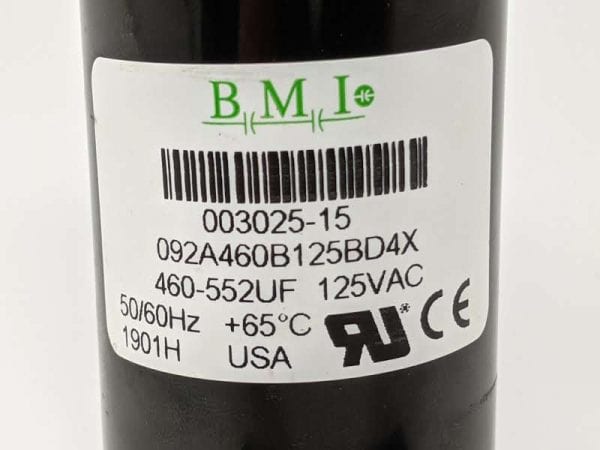
Figure 4. Example label from a start capacitor. The label contains important information including the capacitance range (460 to 552 μF), voltage rating (125 V), and electrical frequency (50 or 60 Hz).
- Capacitance is the amount of stored charge in the unit and is typically measured in microfarads (μF) for motor capacitors. Capacitors must be replaced with similar capacitance μF ratings.
- Voltage rating is based on the peak voltage (V) the capacitor will experience during operation. Voltages vary depending upon use (start or run capacitor).
- Electrical frequency is the frequency of the power coming into the motor. It can be either 60 hertz (Hz) (US) or 50 Hz (Europe and South America). However, many capacitors can operate using either frequency.
- Operating temperature is the maximum operating temperature at which the capacitor is designed to run. Operating at or above this temperature can de-rate the life of the capacitor. Oftentimes this temperature isn’t reported on the label.
- Physical size is important because the capacitor must fit inside the compartment attached to the motor. The metal housing is fabricated to fit tightly around the capacitor and hold it in place. If a smaller body capacitor is used, it could move with the housing and electrically short.
Types of Motor Capacitors
A motor can have a start capacitor, run capacitor, or a combination of both.
Start Capacitor
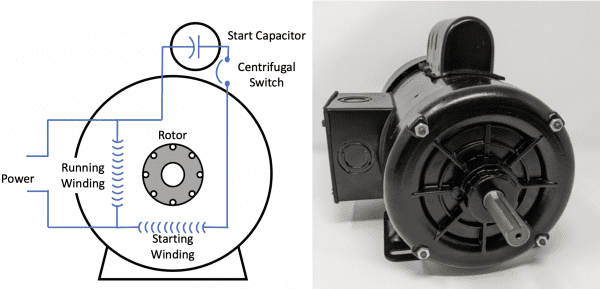
Figure 5. Simplified illustration of a motor with a start capacitor (left); 1 hp motor with a start capacitor (right). (Adapted from MEO, 2015.)
A start capacitor (figure 5) is connected to the motor windings through a centrifugal switch. It is used to increase motor starting torque and allow an electric motor to be cycled on and off rapidly (intermittent or brief use). The centrifugal switch will drop the start capacitor out of the circuit when the motor reaches 75 percent of its full speed. The symbol used for a capacitor in wiring diagrams will have two vertical parallel bars (-||-) or one bar vertical and one curved ( -|(- ) to illustrate electrical polarity, which means it can only be installed with electricity flowing in one direction.
As the motor reaches approximately 75 percent of the total speed, the centrifugal switch (figure 6) opens and disconnects the start capacitor, leaving the motor to run unassisted. Start capacitors are not to be used in continuous duty.
Click on the images below to see them at full scale.
-
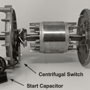
- Figure 6a. Start capacitor connected to a centrifugal switch fixed on the rotor.
-
-
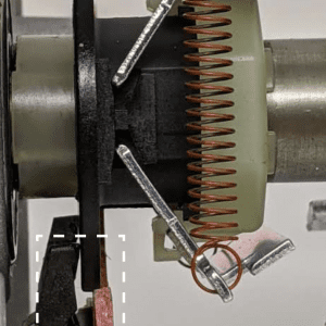
Figure 6b. When the motor is turning below 75 percent of total speed, the switch is closed,
and the start capacitor can energize the motor.
-
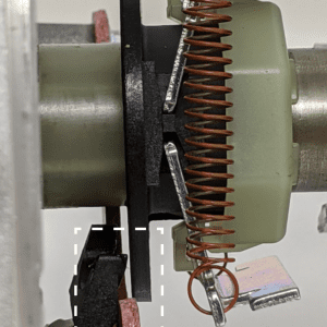
- Figure 6c. As the motor turns above 75 percent of total speed, the switch opens and disconnects the start capacitor to prevent damage.
Figure 7 is a torque/speed curve and demonstrates the amount of extra torque a start capacitor can provide as a function of percent motor speed. You can see the torque drop off when the centrifugal switch opens at 75 percent. If the start capacitor isn’t working, you will not get this boost above 100 percent, and the motor will make a grinding noise and struggle against the start-up torque required to get the load (fan, auger, or other) moving.
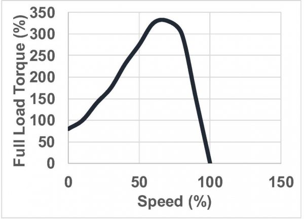
Figure 7. Graph illustrating the percent full-load torque created with a start capacitor as a function of full motor speed
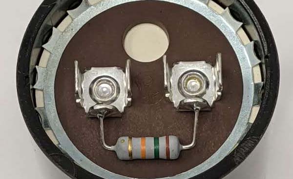
Figure 8. Start capacitors with a bleed-off resistor soldered between the two tabs to dissipate stored energy between uses
Start capacitors typically have the following characteristics:
- They are turned on/off by a centrifugal switch (figure 6).
- They usually have capacitance ratings greater than 70 μF.
- They are typically specified for a capacitance range; example 460 to 552 μF (figure 4).
- They typically have voltage ratings of 125 V, 165 V, 250 V, and 330 V.
- They can have a bleed-off resistor across the terminals to dissipate the stored charge between uses (figure 8).
Run Capacitor
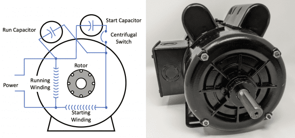
Figure 9. Simplified illustration of a motor with a start and run capacitor (left); 1.5 hp motor with a start and run capacitor housed on top of the motor (right). (Adapted from MEO, 2015.)
A run capacitor (figure 9) is used in single-phase motors to maintain a running torque on an auxiliary coil while the motor is loaded. These capacitors are considered continuous duty while the motor is powered and will remain in the circuit while the start capacitor drops out. Not all single-phase motors have run capacitors.
Run capacitors typically have the following characteristics:
- They usually have capacitance ratings of 1.5 to 100 μF.
- They are typically specified for a single capacitance with a tolerance; example 20 μF ± 6 percent (figure 10).
- They typically have higher voltage ratings of 240 V, 440 V, etc.
How to Test a Motor Capacitor
Motor capacitors can fail for a variety of reasons: normal wear and tear, lightning strikes and power surges, motor deficiencies, and installation of a capacitor with the wrong values (capacitance, voltage, frequency, etc.).
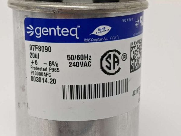
Figure 10. Example label from a run capacitor. The label contains important information including the capacitance (20 μF ± 6%), voltage rating (240 V), and electrical frequency (50 or 60 Hz).
The start capacitor may be the problem if the motor is energized and makes a humming sound but does not rotate or rotates slowly. The run capacitor may be the problem if the motor starts but runs at a higher than stated current load (amps) and overheats.
To determine if your motor capacitors are bad, consult “NPTC Tools of the Trade: Testing a Motor Capacitor” (Extension publication ANR-2783). This document provides a list of required tools and step-by-step instructions to evaluate motor capacitors in question. You can print multiple copies of the motor capacitor evaluation worksheet to guide your capacitor testing and to keep in your maintenance records.
Potential Savings from Checking Capacitors
Table 1 provides three common scenarios and associated costs to replace a 1.5 hp electric motor and a motor capacitor. Scenario 1 shows the activities and costs to replace a motor or capacitor ($268 vs. $26) that the producer has stocked on the farm. Scenario 2 shows the extra cost for a producer to drive to the supply store and replace a motor or capacitor ($304 vs. $62). Scenario 3 shows an approximate cost to hire an electrician to replace the motor or capacitor ($450 vs. $120) if a producer is limited on time, doesn’t know how, or chooses not to make this repair. Replacing a capacitor is 70 to 90 percent cheaper than replacing a motor.
Farm size and age have an influence on the number of maintenance activities a producer must complete to sustain performance. Our example two-house poultry farm has 80-plus electric motors. With the quality of motors today, a producer may replace half of the motors over an 8-to-10-year period.
Table 1. Estimate of Costs to Replace Electric Motors and Capacitors
| Scenario | Units | Unit Cost | Total Cost |
|---|---|---|---|
Scenario 1 | |||
Cost to replace farm-stocked motor | |||
1.5 hp electric motor | 1 motor | $250 | $250 |
Labor to swap motors | 1.5 hr. | $12 | $18 |
| Total | $268 | ||
Cost to replace farm-stocked capacitors | |||
Start capacitor | 1 capacitor | $20 | $20 |
Labor to swap capacitor | 0.5 hr. | $12 | $6 |
Total | $26 | ||
Scenario 2 | |||
Cost to run to the store to replace motor | |||
1.5 hp electric motor | 1 motor | $250 | $250 |
Labor to swap motors | 1.5 hr. | $12 | $18 |
Trip to supply store (round trip) | 2 hrs. | $12 | $24 |
Fuel for trip | 4 gal. | $3 | $12 |
| Total | $304 | ||
Cost to run to the store to replace capacitors | |||
Start capacitor | 1 capacitor | $20 | $20 |
Labor to swap capacitor | 0.5 hr. | $12 | $6 |
Trip to supply store (round trip) | 2 hr. | $12 | $24 |
Fuel for trip | 4 gal. | $3 | $12 |
Total | $62 | ||
Scenario 3 | |||
Cost for electrician to replace motor | |||
1.5 hp electric motor | 1 motor | $250 | $250 |
Labor to swap motors | 1 trip | $200 | $200 |
Total | $450 | ||
Cost for electrician to replace capacitors | |||
Start capacitor | 1 capacitor | $20 | $20 |
Labor to swap capacitor | 1 trip | $100 | $100 |
Total | $120 |
Table 2 shows a comparison of how two producers might handle the failure of these 40 electric motors. Producer A swaps out every motor that fails and stacks the dead motor behind the generator shed. Over the 8-to-10- year period, Producer A replaces 15 motors that were stocked on the farm, 20 motors that required a trip to the supply store, and 5 motors that required an electrician. Producer A spent $12,350 to replace 40 electric motors.
Producer B had the same 40 motors fail on the farm over the same period of time. The difference is that he/ she evaluated the motor capacitors before removing the motor for replacement. Let us assume that Producer B saved half of the motors by replacing dead capacitors. By actively evaluating the failed motors, Producer B saved approximately $6,000 in maintenance costs.
Table 2. Estimated Replacement Costs for Failed Motors
| Producer | Motor Maintenance Activity | Units | Unit Cost | Total Cost |
|---|---|---|---|---|
| Producer A* | ||||
| Scenario 1 | ||||
| Replaced farm-stocked motors | 15 | $268 | $4,020 | |
Bought new motors at store | 20 | $304 | $6,080 | |
Had electrician replace motors | 5 | $450 | $2250 | |
Scenario 2 | ||||
Replaced farm-stocked capacitors | 0 | $26 | $0 | |
Bought new capacitors at store | 0 | $62 | $0 | |
| Had electrician replace capacitors | 0 | $120 | $0 | |
*Replaces a motor every time a failure occurs | Total | $12,350 | ||
Producer B* | ||||
Scenario 1 | ||||
Replaced farm-stocked motors | 15 | $268 | $4,020 | |
Bought new motors at store | 5 | $304 | $1,520 | |
Had electrician replace motors | 0 | $450 | $0 | |
Scenario 2 | Replaced farm-stocked capacitors | 10 | $26 | $260 |
Bought new capacitors at store | 10 | $62 | $620 | |
Had electrician replace capacitors | 0 | $120 | $0 | |
*Tests and replaces motor capacitors to limit motor replacement | Total | $6,420 | ||
Total savings for Producer B over an 8-to-10-year period | $5,930 | |||
Percent Reduction | 48% |
Summary
Before you replace any motor on the farm, check the motor capacitors. Start and run capacitors are important in helping motors under a load to get up to speed quickly. A producer can realize a 70 to 90 percent cost savings by replacing motor capacitors rather than replacing “bad” motors. Our example shows a 48 percent overall cost savings, but exact savings will depend on labor costs, the number of motors that truly fail, and the number that can be repaired with a capacitor.
Safety Warnings
- Always disconnect electrical equipment before inspection and service.
- Always consult an electrician when performing activities on electrical systems.
- By design, motor capacitors store electrical energy. This energy is enough to electrically shock an individual and cause harm. Other injuries, such as head trauma from falling backward, could also occur.
- Always read the manual and follow technical and safety instructions when performing maintenance activities on an electrical system and its components.
- Always wear personal protective equipment (PPE).
Reference
MEO. 2015. Single-phase motors: capacitors start-and-run motor. Machinery equipment online. http://machineryequipmentonline.com/electric-equipment/single-phase-motorscapacitor-start-and-run-motor/
![]()
 Jeremiah Davis, Extension Specialist, Associate Professor, Director, National Poultry Technology Center (NPTC); Jesse Campbell, Extension Specialist, Assistant Extension Professor, NPTC; Danny Miller, County Extension Coordinator, Cherokee County; Kelly Griggs, Research Engineer, NPTC; Martha Sabine Rueda Lastres, Graduate Research Assistant, NPTC; and Carson Edge, Graduate Research Assistant, NPTC
Reviewed August 2023, Start and Run Capacitors for Electric Motors, ANR-2784