Farming
Learn the necessary steps to properly test a motor capacitor on the farm.
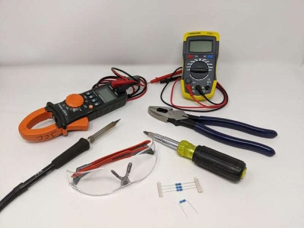
Figure 1. Tools to perform a motor capacitor test: electrical multimeter, capacitance meter (optional), insulated pliers, multi-tool driver, electrical resistors, and soldering iron. Always wear safety glasses.
Before testing can begin, you need to gather the necessary tools to perform a capacitor test (figure 1):
- Electrical multimeter with modes to test continuity and capacitance. Continuity will be identified as a sound logo, and capacitance will be identified with a capacitor logo (-||-) on the multimeter dial.
- Capacitance meter to check the capacitance of a start or run capacitor.
- Multi-tool driver or set of sockets to open the capacitor housing on the motor.
- Insulated pliers to remove the spade connectors from the capacitor tabs and to hold the discharge resistor.
- Electrical resistor (15 to 20k Ohm) to dissipate the electrical charge of the capacitors. An electrically insulated screwdriver is used by electricians to discharge the capacitor, but it is not a recommended method.
- Soldering iron (electric or gas pen) to remove and reattach a bleed-off resistor if attached to the start capacitor.
Steps to Remove Capacitor from the Motor
- Turn off the power and verify that the motor you will be inspecting is disconnected (lock out–tag out). The best way to ensure that the power is disconnected is to physically unplug the motor (figure 2); however, there are many instances where fans have a waterproof switch that shuts the fan off. We recommend shutting off the circuit breaker to the motor as well.
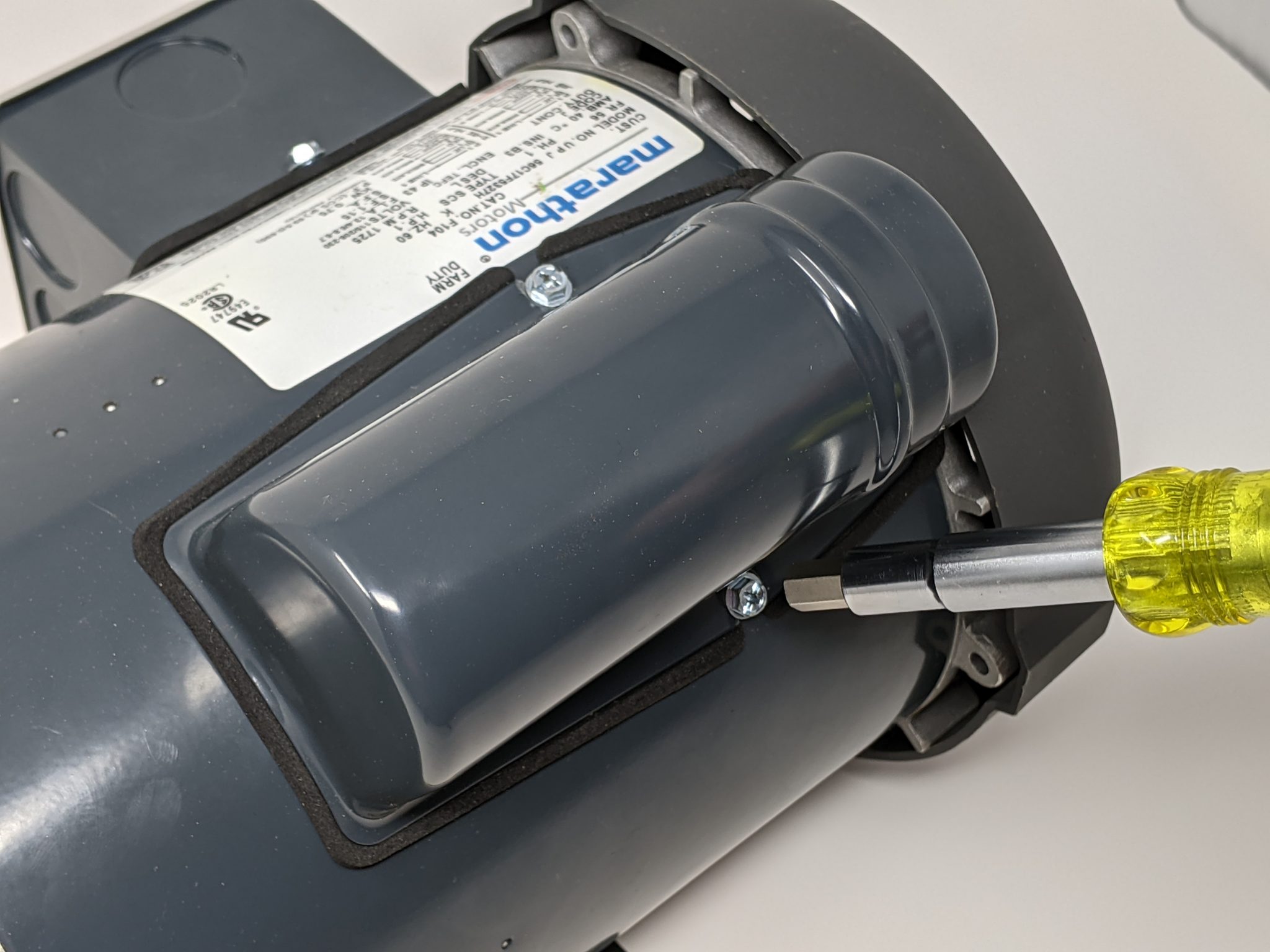
- Find and remove the metal housing that covers the start and/or run capacitor.
- Using a multi-tool driver or sockets, loosen the screws on each side of the housing (figure 3).
- After removing the cover, place the screws back in their location to keep from losing them.
- Take a photo of the capacitor label (figure 4, left) and of the wire color and location (figure 4, right) before removing.
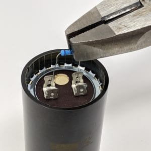
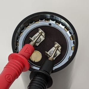
- Remove the wiring spade connectors with insulated pliers (figure 5), being careful not to touch the terminals. For an accurate reading, the capacitor cannot be connected to the motor.
- Using a 20k Ohm electrical resistor (or screwdriver), connect the capacitor terminals to drain the electrical charge (figure 6). This should take a few seconds at most.
- If a bleed-off resistor is soldered between the tabs of a start capacitor (figure 7), you must unsolder one leg of the resistor from one tab to be able to measure capacitance. This is one of the more tedious steps of the process. It looks quicker to cut the resistor leg with your pliers, but it becomes hard to reconnect if the capacitor is good.
-
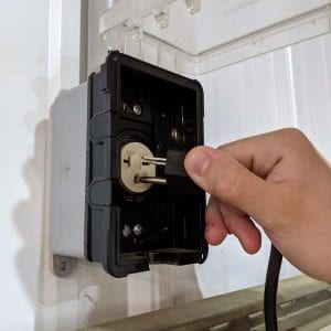
- Figure 2a. Turn off the motor before performing any maintenance. It is best if the motor can be physically unplugged.
-
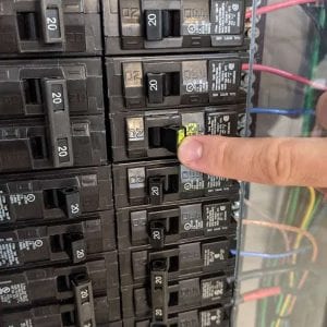
- Figure 2b. Shut off the circuit breaker for the motor circuit as added protection.
-
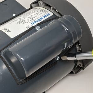
- Figure 3. Start capacitor cover being removed with a multi-tool driver
-
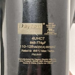
- Figure 4a. Start capacitor label information to be used in the evaluation worksheet.
-
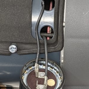
- Figure 4b. Photo to remember wiring arrangement and wire color.
-
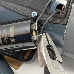
- Figure 5. Electrically insulated pliers are used to remove the wiring connectors from the capacitor tabs. Do not use your fingers as the capacitor might be holding a charge.
-
- Figure 6a. Electrically insulated pliers are used to hold a 20k Ohm resistor across the capacitor tabs to drain any stored energy.
-
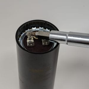
- Figure 6b. An electrically insulated multi- tool is laid across the capacitor terminals to dissipate any stored energy.
-
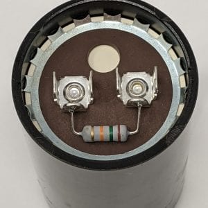
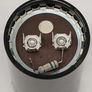
- Figure 7a. Some start capacitors come with a bleed-off resistor soldered between the two tabs.
-
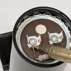
- Figure 7b. Unsolder one leg of the resistor with a soldering iron to disconnect the tabs for testing (Figure 7c.).
-
- Figure 7c. Disconnected tabs for testing.
Testing Motor Capacitors
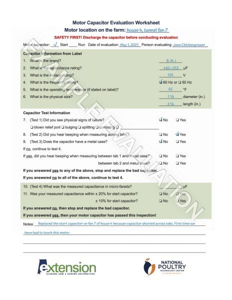
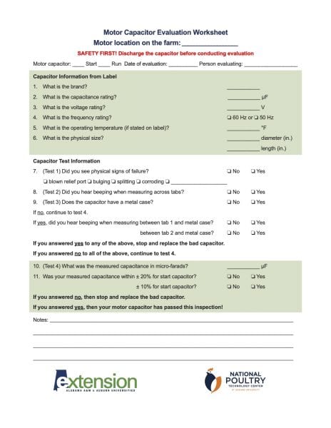
There are four tests to evaluate whether a motor capacitor is good or bad. Use the motor capacitor evaluation worksheet at the end of this document to log the data you gather for each capacitor tested. You and your team can print out these worksheets to develop a maintenance log on your farm.
- Look for signs that the capacitor has blown. If you see signs that the capacitor has blown; that the relief port on the end is blown open (figure 8); or that the case has a bulge, is split open, or is corroded, stop and replace capacitor.
- Test the capacitor to make sure there is no electrical continuity within the capacitor.
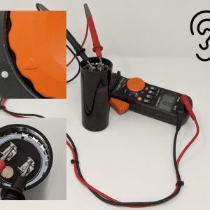
- When using a multimeter, rotate the dial to the continuity label. It usually has a sound waves icon. Check that it is working by touching the two leads of the multimeter to one another; you will hear a beeping sound.
- Place the two leads on each of the two terminals to take a reading (figure 9).
- If you hear a beeping sound, the capacitor is allowing current to flow across the dielectric layers and the capacitor is no good. Stop and replace capacitor.
- Test the capacitor for shorts between the capacitor material and the case.
- Skip this step if the capacitor housing is plastic.
- When using a multimeter, rotate the dial to the continuity label. It usually has a sound waves icon. Check that it is working by touching the two leads of the multimeter to one another; you will hear a beeping sound.
- Place one lead on the first tab and the second lead on the metal case to take a reading (figure 10, left). Repeat to check the second tab to the metal case (figure 10, right).
- If you hear a beeping sound, the capacitor is allowing current to flow from the dielectric material to the case and the capacitor is no good. Stop and replace capacitor.
- Test to measure the capacitance of the capacitor.
- If you are using an electrical multimeter, rotate the dial to the capacitance symbol (-||-). We have found it challenging to get a good reading from some multimeters that have the capacitance capability, and some multimeters may not have the ability to measure capacitance. A capacitance meter can be used to complete this test.
- Make sure that the red and black leads are in the proper locations (if your meter has multiple slots for the leads) on the meter to test capacitance. The red lead should plug into the capacitance symbol if present.
- Place the two leads on each of the two terminals to take a reading.
- Capacitance readings should fall within the stated microfarads (μF) rating on the label.
- The start capacitor should be within ± 20 percent of stated capacitance.
- The run capacitor should be within ±10 percent of stated capacitance.
- If the reading is at the edge or outside of these limits, stop and replace capacitor.
-
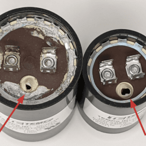
- Figure 8. Two capacitors with the relief port blown (highlighted with arrow). This relief port is designed to fail to keep the capacitor from exploding. These should be discarded after taking a photo of the label.
-
- Figure 9a. To test electrical continuity between the dielectric layers, turn the multimeter to the continuity position (Figure 9b) and then place one multimeter probe on each of the two tabs (Figure 9c). A beeping sound indicates that the capacitor is bad and should be replaced.
-
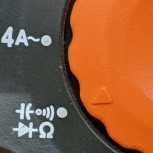
- Figure 9b. Turn the multimeter to the continuity position.
-
- Figure 9c. Place one multimeter probe on each of the two tabs.
-

- Figure 10a. To test electrical continuity between the dielectric layers and the capacitor housing, place one multimeter probe on the first tab and the second probe on the housing.
-

- Figure 10b. Move the first probe to the second tab and keep the second probe on the housing. If you hear a beeping sound on either tab, the capacitor is bad and should be replaced.
Replacing Motor Capacitors
Once you have determined that the start or run capacitor is bad, you need to replace the damaged unit with a new capacitor.
- Record test capacitor label information. Make sure you have taken a photo of the capacitor label or have entered the information on the motor capacitor evaluation worksheet.
- The replacement capacitor must have the same capacitance rating.
- If a lower capacitance (<μF) is used in a start capacitor, the motor will have reduced starting torque and rpm and lower efficiency.
- If a higher capacitance (> μF) is used in a start capacitor, the motor may have the same issues along with overheating due to higher currents being pushed through the windings, potentially damaging the motor.
- If the wrong capacitance is used for a run capacitor, it will cause the magnetic field around the motor to be irregular, causing the motor to hesitate at spots under full load. This hesitation can cause the motor to be noisy, less efficient, and prone to overheating.
- The replacement capacitor must have similar or larger voltage ratings to the installed capacitor.
- A 440 V motor run capacitor can be used for a 370 V motor run capacitor.
- A370 V motor run capacitor cannot be used in place of a 440 V motor run capacitor.
- A370/440 V rating means that the same capacitor can be used for both voltages.
- The replacement capacitor must be similar in physical size. The new capacitor must fit snuggly in the housing. If the diameter and/or length are smaller, the capacitor can slide and short the tabs on the housing.
- Label the replacement capacitor. Use a paint pen or marker and tape to label the replacement capacitor (figure 13). This will make it easier to track what has been tested and replaced and to identify continued issues with this motor.
To learn more about motor capacitors and their function, see Extension publication “Start and Run Capacitors for Electric Motors,” ANR-2784.
-
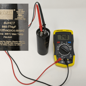
- Figure 11. A capacitance meter is shown with the two probes placed on the two capacitor tabs. This capacitor label shows a capacitance of 645 to 774 μF. The meter is reading a capacitance of 748 μF, which is in the acceptable range. The capacitor is good.
-
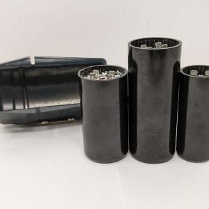
- Figure 12. Three start capacitors with different lengths and diameters. The center capacitor has the correct physical dimensions to fit snuggly in the metal housing on the left.
-
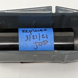
- Figure 13. Label the replacement capacitor with a paint pen or tape and marker. This will allow easy identification if further problems occur with this motor.
Safety Warning
- Always disconnect electrical equipment prior to inspection and service.
- Always consult an electrician when performing activities on electrical systems.
- By design, motor capacitors store electrical energy. This energy is enough to electrically shock an individual and cause harm. Other injuries, such as head trauma from falling backward, could also occur.
- Always read the manual and follow technical and safety instructions when performing maintenance activities on an electrical system and its components.
- Always wear personal protective equipment (PPE).
![]()
 Jeremiah Davis, Extension Specialist, Associate Professor, Director, National Poultry Technology Center (NPTC); Jesse Campbell, Extension Specialist, Assistant Extension Professor, NPTC; Danny Miller, County Extension Coordinator, Cherokee County; Kelly Griggs, Research Engineer, NPTC; Martha Sabine Rueda Lastres, Graduate Research Assistant, NPTC; and Carson Edge, Graduate Research Assistant, NPTC
New July 2021, NPTC Tools of the Trade: Testing a Motor Capacitor, ANR-2783