Farming
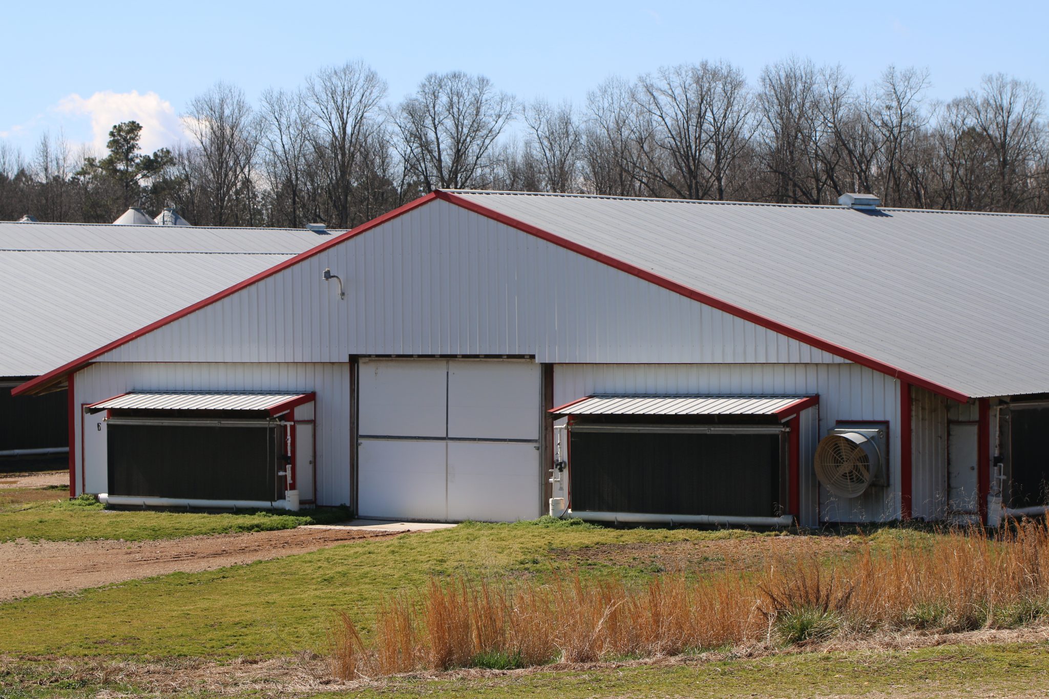
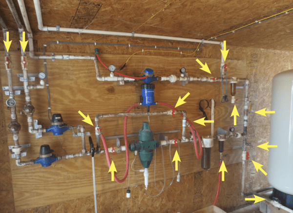
Figure 1. Yellow arrows highlight 15 valves used in this water manifold feeding a 40 x 500 commercial broiler house.
As we repair or add on to our existing water supply systems, we often don’t think about the types of fixtures and valves we use. We often choose replacement valves from what is available on the farm or what is cheapest from the supply store. This publication provides information for making educated choices for your poultry house plumbing.
In the summer months, water capacity always becomes a concern for commercial broiler growers as bird consumption and evaporative cooling systems tax farm water supplies. As we repair or add on to our existing water supply systems, we often don’t think about the types of fixtures and valves we use. We often choose replacement valves from what is available on the farm or what is cheapest from the supply store. Figure 1 shows the water panel of a 40-by-500-foot commercial broiler house with yellow arrows highlighting 15 valves or hose bibs. This manifold has 10 PVC and 3 brass ball valves and 2 brass quarter-turn hose bibs, which begs the question: is it safe to assume that the flow rate out of these valves is the same?
Table 1 shows the results of an experiment to evaluate how five types of 3⁄4-inch valve/hose bibs performed in a flow test compared to an open pipe. The five examples were chosen because they represent common valves used on farms, they were readily available at supply stores, and they illustrate factors to consider when purchasing a valve.
Table 1. Valves Used in This Study
| Valve | Description | Type | Material | Nominal Size (in.) | Approx. Cost |
|---|---|---|---|---|---|
| 1 | PVC ball valve | Ball | PVC | 3⁄4 | $2.98 |
| 2 | Brass ball valve | Ball | Brass | 3⁄4 | $14.48 |
| 3 | Qtr-turn hose bibb | Ball | Brass | 3⁄4 | $14.99 |
| 4 | Hose bibb 1 | Stop/globe | Brass | 3⁄4 | $16.99 |
| 5 | Hose bibb 2 | Stop/globe | Brass | 3⁄4 | $9.99 |
The fixture used in the experiment consisted of a flow control valve, pressure regulator, calibrated water meter, pressure gauge, and the test valve (figure 2). The pressure regulator was set to 40 pounds per square inch (psi). Three replications of each valve/hose bibb were fastened to the test fixture using a union. Open pipe flow rate (gallons per minute [gpm]) was incrementally increased using a flow-control valve from 0 to 15.5 GPM for each valve tested.
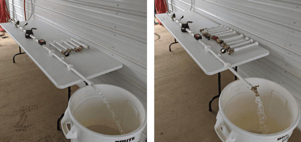
Figure 2. The flow test fixture consisted of a flow control valve, pressure regulator, pressure gauge, calibrated water meter, digital flow meter, pressure gauge, and test valve. Each of the five valve types were connected to the union at the end of the table for testing. Shown is testing open pipe flow with no valve (left) and hose bibb 1 (right) with the same water supply.
The left side of figure 3 shows a side profile of each valve tested. A vertical cross-section was cut through each valve, as shown on the right, to show the internal components and to determine the smallest cross- sectional area the water must flow through. The smallest diameter in each valve is identified by an arrow. Also shown is the valve entrance to show visible restrictions.
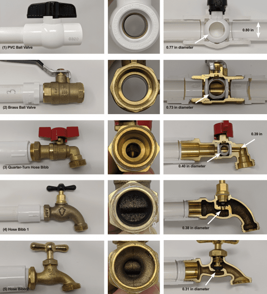
Figure 3. Side profile (left), valve entrance view (center), and internal cutaway of each valve tested.
In a pipe system, a pressure drop occurs when frictional forces act against a fluid (water or gas) flowing through a pipe or valve. As the diameter of the pipe gets smaller or the fluid has to make tight turns, such as in a hose bibb, it takes more pressure (power) to maintain a given flow rate. The pressure drop across a valve is determined by subtracting the outlet pressure from the inlet pressure as shown in figure 4. If the valve is open to the outside air like a hose bibb filling a bucket, the outlet pressure would be 0 gauge pressure.
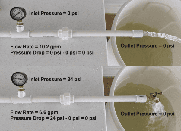
Figure 4. Comparison of the pressure drop developed from an open pipe (top) and hose bibb 2 (bottom). With the same supply, the addition of hose bibb 2 increased the pressure drop to 24 psi and reduced the flow rate by 3.6 gpm, or 35.3 percent.
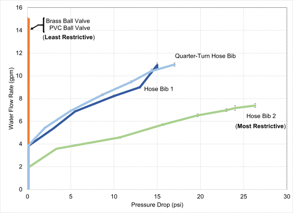
Figure 5. Pressure (psi) required to produce water flow rates (gpm) for each valve/ hose bibb tested. For demonstration purposes only. Not for construction or design standards.
Figure 5 shows output water flow rates (GPM) and the associated pressure drop (psi) for each valve or hose bibb tested. Hose bibb 2 required pressure to move water above 2 GPM while the remaining valves did not require pressure until flow increased above 4 GPM. Above 4 GPM, the quarter-turn hose bibb and hose bibb 1 require pressure to continue to increase flow. Generally, the higher the flow rate, or GPM, through a valve restriction, the greater the pressure drop generated.
The PVC and brass ball valves had the least pressure drop of the valves tested as there were minimal internal restrictions. In figure 3, the size of the ports in the PVC and stainless steel balls were similar in size to the pipe diameter, as shown in the sliced sections. The PVC and brass ball valves had small reductions in cross-sectional area of 7.4 and 16.3 percent, respectively, as shown in table 2. The ball valves lose only 3 percent of the open pipe flow rate.
Table 2. Cross-Sectional Area and Flow Rate Relative to Supply Piping and Open Pipe Flow Rate
2 Smallest cross-sectional area (in2) in the valve body
3 Reduction of the cross-sectional area as a percentage of the inside diameter of 3⁄4-in schedule 40 PVC (0.80-in)
4 Maximum output flow rate tested for each valve
5 Reduction in flow rate as a percentage of maximum open pipe flow (15.5 gpm) tested
| Valve | Description | Smallest Diameter (in.)1 | Cross-Sectional Area (in.2)2 | Reduction in CSA (%)3 | Output flow rate (gpm)4 | Reduction in flow rate (%)5 |
|---|---|---|---|---|---|---|
| 1 | PVC ball valve | 0.77 | 0.46 | -7.4 | 15.0 | -3.1 |
| 2 | Brass ball valve | 0.73 | 0.42 | -16.3 | 15.0 | -3.1 |
| 3 | Qtr-turn hose bibb | 0.39 | 0.12 | -76.5 | 11.0 | -28.9 |
| 4 | Hose bibb 1 | 0.38 | 0.11 | -77.6 | 10.7 | -31.1 |
| 5 | Hose bibb 2 | 0.31 | 0.08 | -84.7 | 7.4 | -52.3 |
Though technically a ball valve, the quarter-turn hose bibb developed a similar pressure drop to hose bibb 1. The small internal diameter of the quarter-turn valve reduced the cross-sectional area by 76.5 percent. The quarter-turn hose bibb loses roughly a third (28.9 percent) of the open pipe flow rate. Many versions of these quarter-turn bibbs have been used in water manifolds and have examples with smaller internal diameters than those tested here.
Hose bibbs 1 and 2 were the most restricted of all the valves because they had the smallest cross-sectional areas. The reduction in CSA was 77.6 percent and 84.7 percent for hose bibb 1 and hose bibb 2, respectively. The larger-bodied hose bibb 1 loses roughly a third (31.1 percent) of the open pipe flow rate. The smaller- bodied hose bibb 2 loses roughly half (52.3 percent) of the open pipe flow rate. The flow rate of hose bibb 2 appears to be leveling off below 8 GPM. From a practical standpoint, no more than 8 GPM can be expected out of hose bibb 2 regardless of how much pressure continues to add. Hose bibb 2 was the least expensive brass bibb found, and it is often used for a variety of tasks on broiler farms such as tap to fill buckets, supply water for the evaporative cooling system, and to connect medicators.
When purchasing valves from the supply store for this experiment, we found that valves in a bin were often the same brand and looked very similar to what we had, but during the test, the internal CSA and the measured flow rate would be different, proving that valves that may look the same and have the same handles can have very different bodies. If you can see a large restriction at either end of the valve or hose bibb, you can also expect to see a reduction in output flow rate.
In conclusion, just because a valve fits does not mean that it is the right one for the job. If you think you have a water shortage to birds or evaporative pads on the farm, make sure you consider the water valve as a possible restriction. In some cases, the plumbing supply may be adequate, but components inside the valve, hidden to the naked eye, are causing a restriction. Hose bibbs should not be used in line with further plumbing as the restriction can negatively affect everything downstream during periods of high water demand. Ball valves should be used anywhere you expect more plumbing downstream as they minimize restrictions to flow. The next time you are shopping for a water valve, shop with performance in mind and not just the cost or the size of the pipe fitting alone.
For more information on poultry housing, visit poultryhouse.com.
Download a PDF of Do Your Valves and Hose Bibs Restrict Water Capacity?, ANR-2721.