Dairy
Waste storage ponds are used on many dairy, swine, and poultry layer farms. Storage pond slurry can be an effective part of the waste management plan. Learn the proper procedure for calibrating traveling guns for slurry irrigation.
Waste storage ponds are used on many dairy, swine, and poultry layer farms in Alabama as part of the waste management system. These ponds collect and hold animal waste generated at these operations. Most waste storage ponds are designed to fill up and be emptied at least twice and in some cases three times a year. If waste storage ponds fill up and overflow, they will pollute water sources. On the other hand, if storage pond slurry is applied to cropland, it can be an effective part of the waste management plan.
Land application of storage pond slurry with sprinkler irrigation equipment is becoming more common in Alabama. This is a good management practice for two reasons: it allows recycling of on-farm nutrients, and it reduces the pollution of the surrounding environment.
Land application should match the fertilizer content of slurry to the crop requirements and soil characteristics. Fertilizer concentrations in animal waste slurry are quite high, ranging from more than 500 pounds of total nitrogen per acre inch for dairy slurry to more than 800 pounds of total nitrogen per acre inch for swine slurry. Poultry layer slurry may contain twice these levels of total nitrogen per acre inch. When irrigation-applied, less than half of the total nitrogen is plant available. Controlling the application depth of animal waste slurry irrigation is essential to manage off-farm pollution and receive maximum available benefits from fertilizer in the slurry.
To control the amount of slurry and nutrients being applied to a field, the operator must properly calibrate slurry irrigation equipment. Calibrating fertilizer application equipment is not new to farmers, but calibrating irrigation equipment may be a relatively new procedure for those unfamiliar with irrigation. Traveling irrigation guns are commonly used for waste slurry application and are the most difficult type of irrigation system to calibrate.
Calibration Procedure
The following example illustrates the calibration procedure for traveling guns. It applies to both waste slurry and wastewater irrigation using traveling guns.
(1) Choose nutrient application rate based on the crop grown, soil characteristics, and the existing nutrient level.
Example: 150 lb. N/acre
Your numbers: _____ lb. N/acre
(2) Determine waste slurry application rate in gallons per acre (gal./acre). Divide the nutrient application rate from Step 1 by the pounds of plant-available nutrient per thousand gallons of slurry (determined by actual test or by site or operation-type history); then, multiply by 1,000.
Example: 150 lb. N/acre ÷ 17 lb. N/1,000 gal. × 1,000 = 8,823 gal./acre
Your numbers: _____ lb. N/acre ÷ ____ lb. N/1,000 gal. × 1,000 = ______ gal./acre
(3) Determine in./acre of slurry to apply. Divide gal./acre from Step 2 by 27,154 gal./acre-in.
Example: 8,823 gal./acre ÷ 27,154 gal./acre-in. = .32 in.
Your numbers: ______ gal./acre ÷ 27,154 gal./acre-in. = ____ in.
(4) From table 1, select diameter of throw for existing nozzle size, expected psi, and GPM.* Multiply by 0.7 for correct travel lane spacing.**
Example: 1.0 -in. nozzle at 60 psi, 225 GPM, Lane spacing = 0.7 × 325 -ft. diameter of throw = 227 ft.
Your numbers: ____-in. nozzle at ____ psi, ____ GPM, Lane spacing = 0.7 × _____-ft. diameter of throw = ____ ft.
(5) Calculate travel speed*** (ft./min.) required. Multiply 1.6 times GPM. Divide by lane spacing (ft.); then divide by inches applied.
Example: Travel speed = 1.6 × 225 GPM ÷ 227 -ft. lane spacing ÷ 0.32 in. = 4.95 ft./min.
Your numbers: Travel speed = 1.6 × _____ GPM ÷ _____-ft. lane spacing ÷ _____ in. = _____ ft./min.
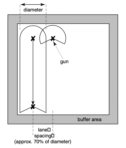
Figure 1. Traveling gun layout
*Gallons per minute flow rate (GPM) from any particular nozzle can easily be determined by pressure at the nozzle. Most traveling guns are equipped by the manufacturer with a 1 ⁄4-inch nipple tap located on the gun body. A pressure gauge can easily be attached at this location and used to check gun nozzle operating pressure. Table 1 gives typical flow rates and expected diameters of throw (24° gun trajectory angle) for various size taper bore nozzles used in traveling guns. This chart can be used to determine traveling gun flow rate at actual operating pressure if a manufacturer’s chart is not available.
**Travel lane spacing should be 70 percent (0.7) of the nozzle throw diameter for uniform wastewater application. See Figure 1 for a typical traveling gun layout.
***Travel speed of the gun cart is the most complicated of the traveling gun application rate factors to calculate. Travel speed can be calculated from mathematical formula, from information in Table 2, or from manufacturer’s data on particular travel guns.
Table 1. Typical Nozzle Flow Rates and Diameters of Throw for 2-Inch Taper Bore Nozzle with 24° Trajectory
| PSI | Nozzle 0.7" GPM | Nozzle 0.7" DIA | Nozzle 0.8" GPM | Nozzle 0.8" DIA | Nozzle 0.9" GPM | Nozzle 0.9" DIA | Nozzle 1.0" GPM | Nozzle 1.0" DIA | Nozzle 1.1" GPM | Nozzle 1.1" DIA | Nozzle 1.2" GPM | Nozzle 1.2" DIA | Nozzle 1.3" GPM | Nozzle 1.3" DIA |
|---|---|---|---|---|---|---|---|---|---|---|---|---|---|---|
| 50 | 100 | 250' | 130 | 270' | 165 | 290' | 205 | 310' | 255 | 330' | 300 | 345' | 350 | 360' |
| 60 | 110 | 265' | 143 | 285' | 182 | 305' | 225 | 325' | 275 | 345' | 330 | 365' | 385 | 380' |
| 70 | 120 | 280' | 155 | 300' | 197 | 320' | 245 | 340' | 295 | 360' | 355 | 380' | 414 | 395' |
| 80 | 128 | 290' | 165 | 310' | 210 | 335' | 260 | 355' | 315 | 375' | 380 | 395' | 445 | 410' |
| 90 | 135 | 300' | 175 | 320' | 223 | 345' | 275 | 365' | 335 | 390' | 405 | 410' | 475 | 425' |
| 100 | 143 | 310' | 185 | 330' | 235 | 355' | 290 | 375' | 355 | 400' | 425 | 420' | 500 | 440' |
| 110 | 150 | 320' | 195 | 340' | 247 | 365' | 305 | 385' | 370 | 410' | 445 | 430' | 525 | 450' |
| 120 | 157 | 330' | 204 | 350' | 258 | 375' | 320 | 395' | 385 | 420' | 465 | 440' | 545 | 460' |
Table 2. Wastewater Applied by Traveling Gun Sprinklers*
**The travel lane spacing should be approximately 70 percent of the sprinkler’s coverage diameter. The coverage diameter can be determined from the manufacturer’s literature or by measurement. Refer to Figure 1 for a diagram of a traveling gun layout.
| Sprinkler Flow Rate (GPM) | Travel Lane Spacing (ft.)** | Travel Speed - 0.4 ft./min. | Travel Speed - 0.5 ft./min. | Travel Speed - 1 ft./min. | Travel Speed - 2 ft./min. | Travel Speed - 4 ft./min. | Travel Speed - 6 ft./min. | Travel Speed - 8 ft./min. | Travel Speed - 10 ft./min. |
|---|---|---|---|---|---|---|---|---|---|
| Wastewater Applied (in.) | Wastewater Applied (in.) | Wastewater Applied (in.) | Wastewater Applied (in.) | Wastewater Applied (in.) | Wastewater Applied (in.) | Wastewater Applied (in.) | Wastewater Applied (in.) | ||
| 100 | 150 | 2.7 | 2.1 | 1.1 | 0.5 | 0.3 | 0.2 | 0.1 | 0.1 |
| 100 | 200 | 2.0 | 1.6 | 0.8 | 0.4 | 0.2 | 0.1 | 0.1 | 0.1 |
| 100 | 250 | 1.6 | 1.3 | 0.6 | 0.3 | 0.2 | 0.1 | 0.1 | 0.1 |
| 100 | 300 | 1.3 | 1.1 | 0.5 | 0.3 | 0.1 | 0.1 | 0.1 | 0.1 |
| 200 | 150 | 5.4 | 4.3 | 2.1 | 1.1 | 0.5 | 0.4 | 0.3 | 0.2 |
| 200 | 200 | 4.0 | 3.2 | 1.6 | 0.8 | 0.4 | 0.3 | 0.2 | 0.2 |
| 200 | 250 | 3.2 | 2.6 | 1.3 | 0.6 | 0.3 | 0.2 | 0.2 | 0.1 |
| 200 | 300 | 2.7 | 2.1 | 1.1 | 0.5 | 0.3 | 0.2 | 0.1 | 0.1 |
| 300 | 200 | 6.0 | 4.8 | 2.4 | 1.2 | 0.6 | 0.4 | 0.3 | 0.2 |
| 300 | 250 | 4.8 | 3.9 | 1.9 | 1.0 | 0.5 | 0.3 | 0.2 | 0.2 |
| 300 | 300 | 4.0 | 3.2 | 1.6 | 0.8 | 0.4 | 0.3 | 0.2 | 0.2 |
| 300 | 350 | 3.4 | 2.8 | 1.4 | 0.7 | 0.3 | 0.2 | 0.2 | 0.1 |
| 400 | 200 | 8.0 | 6.4 | 3.2 | 1.6 | 0.8 | 0.5 | 0.4 | 0.3 |
| 400 | 250 | 6.4 | 5.1 | 2.6 | 1.3 | 0.6 | 0.4 | 0.3 | 0.3 |
| 400 | 300 | 5.4 | 4.3 | 2.1 | 1.1 | 0.5 | 0.4 | 0.3 | 0.2 |
| 400 | 350 | 4.6 | 3.7 | 1.8 | 0.9 | 0.5 | 0.3 | 0.2 | 0.2 |
| 500 | 250 | 8.0 | 6.4 | 3.2 | 1.6 | 0.8 | 0.5 | 0.4 | 0.3 |
| 500 | 300 | 6.7 | 5.4 | 2.7 | 1.3 | 0.7 | 0.4 | 0.3 | 0.3 |
| 500 | 350 | 5.7 | 4.6 | 2.3 | 1.1 | 0.6 | 0.4 | 0.3 | 0.2 |
| 500 | 400 | 5.0 | 4.0 | 2.0 | 1.0 | 0.5 | 0.3 | 0.3 | 0.2 |
| 600 | 250 | 9.6 | 7.7 | 3.9 | 1.9 | 1.0 | 0.6 | 0.5 | 0.4 |
| 600 | 300 | 8.0 | 6.4 | 3.2 | 1.6 | 0.8 | 0.5 | 0.4 | 0.3 |
| 600 | 350 | 6.9 | 5.5 | 2.8 | 1.4 | 0.7 | 0.5 | 0.3 | 0.3 |
| 600 | 400 | 6.0 | 4.8 | 2.4 | 1.2 | 0.6 | 0.4 | 0.3 | 0.2 |
| 700 | 300 | 9.4 | 7.5 | 3.7 | 1.9 | 0.9 | 0.6 | 0.5 | 0.4 |
| 700 | 350 | 8.0 | 6.4 | 3.2 | 1.6 | 0.8 | 0.5 | 0.4 | 0.3 |
| 700 | 400 | 7.0 | 5.6 | 2.8 | 1.4 | 0.7 | 0.5 | 0.4 | 0.3 |
| 700 | 450 | 6.2 | 5.0 | 2.5 | 1.2 | 0.6 | 0.4 | 0.3 | 0.2 |
Checking Gun Cart Speed
Checking actual traveling gun cart speed is a simple matter. You’ll need two flags, a 100-foot tape, and a wristwatch with a minute and second indicator. Set up the gun, and extend the hose. Then:
- Measure off a 100-foot distance along the gun cart travel path and mark with the flags.
- Use a marker, ribbon, or string to mark a point on the retracting hose or cable that is pulling the gun cart.
- During traveling gun irrigation operation, measure and record the time in minutes and seconds required by the ribbon to travel the measured 100-foot distance.
- Convert travel time in minutes and seconds to minutes and partial minutes
- (minutes and seconds = whole minutes + seconds ⁄ 60).
- Example: 1 minute, 27 seconds = 1 + 27 ⁄ 60 = 1 + 0.45 = 1.45 minutes
- Divide the travel distance (100 feet) by the travel time in minutes to get travel speed in feet per After determining the travel speed, adjust the speed control as necessary to get the desired travel speed.
Adjusting Gun Cart Speed
After determining travel speed required, either from the chart or by mathematical calculation, adjust gun cart speed in the field to this desired speed. Since travel speed is so critical for slurry and wastewater irrigation, use only those traveling guns with easily adjustable speed control and speed compensation. Traveling guns with knob adjustments for a dial readout and with mechanical linkage speed compensation seem to be the most reliable.
Ted W. Tyson, Extension Biosystems Engineer, Professor, Biosystems Engineering, Auburn University, and Perry L. Oakes, State Conservation Engineer, Natural Resources Conservation Service
Reviewed July 2024, Calibrating Traveling Guns for Slurry Irrigation, ANR-0925